3D printed home brushless motor
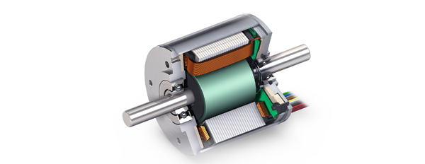
Here we are going to build a homemade brushless motor. First we will see how a brushless motor works, types of brushless motors and finally the building itself. This motor is 3D printed but there are a lot of ways to make your own homemade brushless motor if you don't have a 3D printer.
Brushless motor
Brushless DC electric motor (BLDC motors, BL motors) also known as electronically commutated motors (ECMs, EC motors) are synchronous motors that are powered by a DC electric source via an integrated inverter/switching power supply, which produces an AC electric signal to drive the motor. In this context, AC, alternating current, does not imply a sinusoidal waveform, but rather a bi-directional current with no restriction on waveform. Additional sensors and electronics control the inverter output amplitude and waveform (and therefore percent of DC bus usage/efficiency) and frequency (i.e. rotor speed).
The rotor part of a brushless motor is often a permanent magnet synchronous motor, but can also be a switched reluctance motor, or induction motor[citation needed].
Brushless motors may be described as stepper motors; however, the term "stepper motor" tends to be used for motors that are designed specifically to be operated in a mode where they are frequently stopped with the rotor in a defined angular position. This page describes more general brushless motor principles, though there is overlap.
Construction types
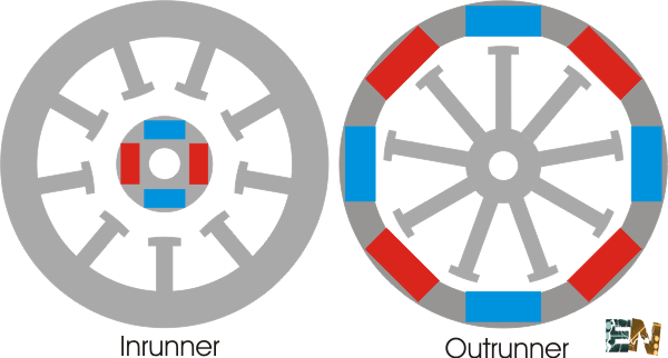
Brushless motors can be constructed in several different physical configurations: In the 'conventional' (also known as inrunner) configuration, the permanent magnets are part of the rotor. Three stator windings surround the rotor. In the outrunner (or external-rotor) configuration, the radial-relationship between the coils and magnets is reversed; the stator coils form the center (core) of the motor, while the permanent magnets spin within an overhanging rotor which surrounds the core. The flat or axial flux type, used where there are space or shape limitations, uses stator and rotor plates, mounted face to face. Outrunners typically have more poles, set up in triplets to maintain the three groups of windings, and have a higher torque at low RPMs. In all brushless motors, the coils are stationary.
Winding types
Where 9N is for 9 stators and 12P is for 12 poles. This is the typical winding used in CD-ROM motors and it's usually terminated Wye (Star).
It is the first winding scheme that many motor builders and rewinders will encounter. It is also the easiest winding to do, since all teeth are wound the same direction, i.e. ABCABCABC.
Here is the most common winding scheme of all, since it is used in the majority of model outrunner motors that are currently being manufactured.
The dLRK scheme is a derivative of the LRK winding scheme, which put outrunner brushless motors on the map.
Connect together: Start A - End C, Start B - End A , Start C - End B.
Here is an interesting mutation of the dLRK scheme, no doubt aimed at making termination of the windings easier and neater. It is my favourite for winding 12N14P motors.
Note how the starts and ends of the phases that need to be connected together, exit from the same slots, making the termination process totally fool-proof.
This is where the 'brushless revolution' started. The LRK winding scheme will always be remembered as being the 'grandfather' of outrunner brushless motors.
'LRK' is an acronym that comes from the names of the three men who popularized the outrunner motor: Lucas, Retzbach and Küfuss. In 2001 they documented the use of this winding scheme for model airplane motors. And as they say in the classics, 'the rest is history'.
Connect together: Start A - End C, Start B - End A , Start C - End B.
Building our Homemade 3D printed Brushless motor
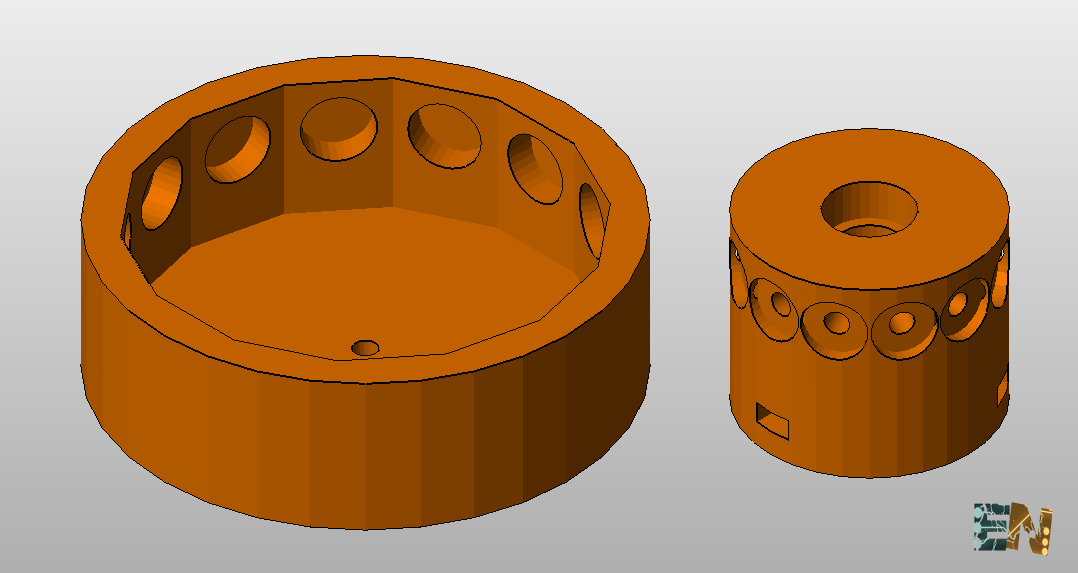
First of all you have to download the 3D .stl files and print them. You can dwonload the files in the link below.
You can download the
![]()
 >
>
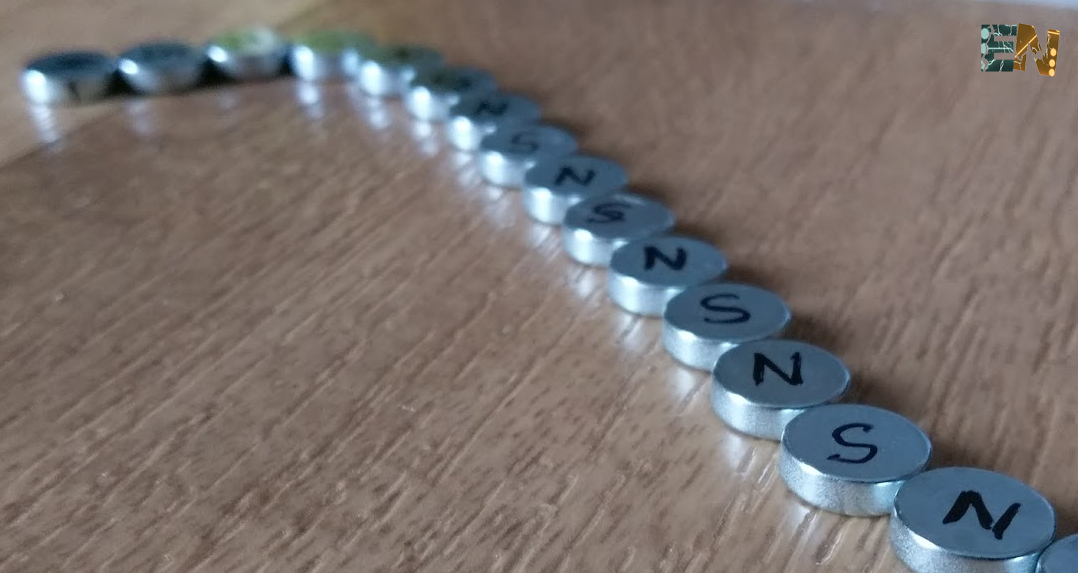
Print the two parts using PLA material, 4 perimeters and 25 infill. Once you have your body we can start the next part. We will use neodymium roumd magnets size 10 by 3 mm. To find whcih pole of each magnet is we put them one to each other side to side. If the magnet wants to spin around, that means that the faces are the same pole and we don't want that. We want to have one north pole then one south then other north etc...
 >
>
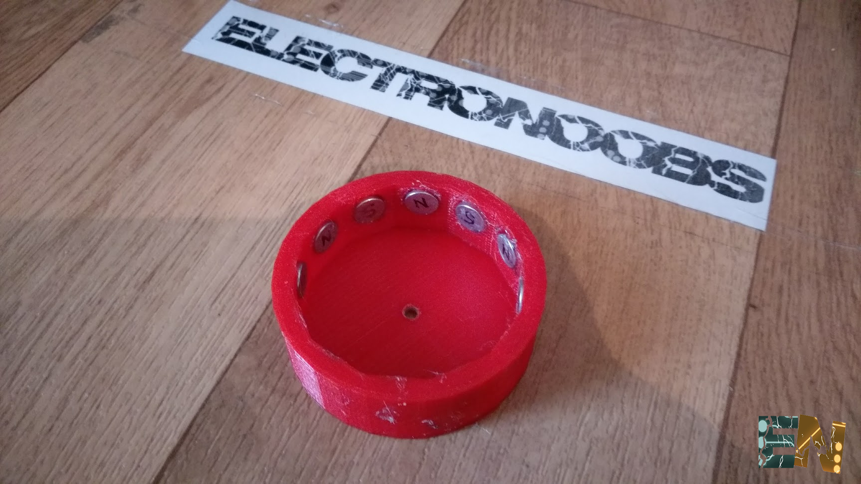
Once you have 14 magnets in a row start and mark each magnet with N and S. It doesn't matter whuch is sout and which is north, the imoportant thing is that one is the oposite of the next one. Now we can start put this magnets in the interior of the printet part.
 >
>
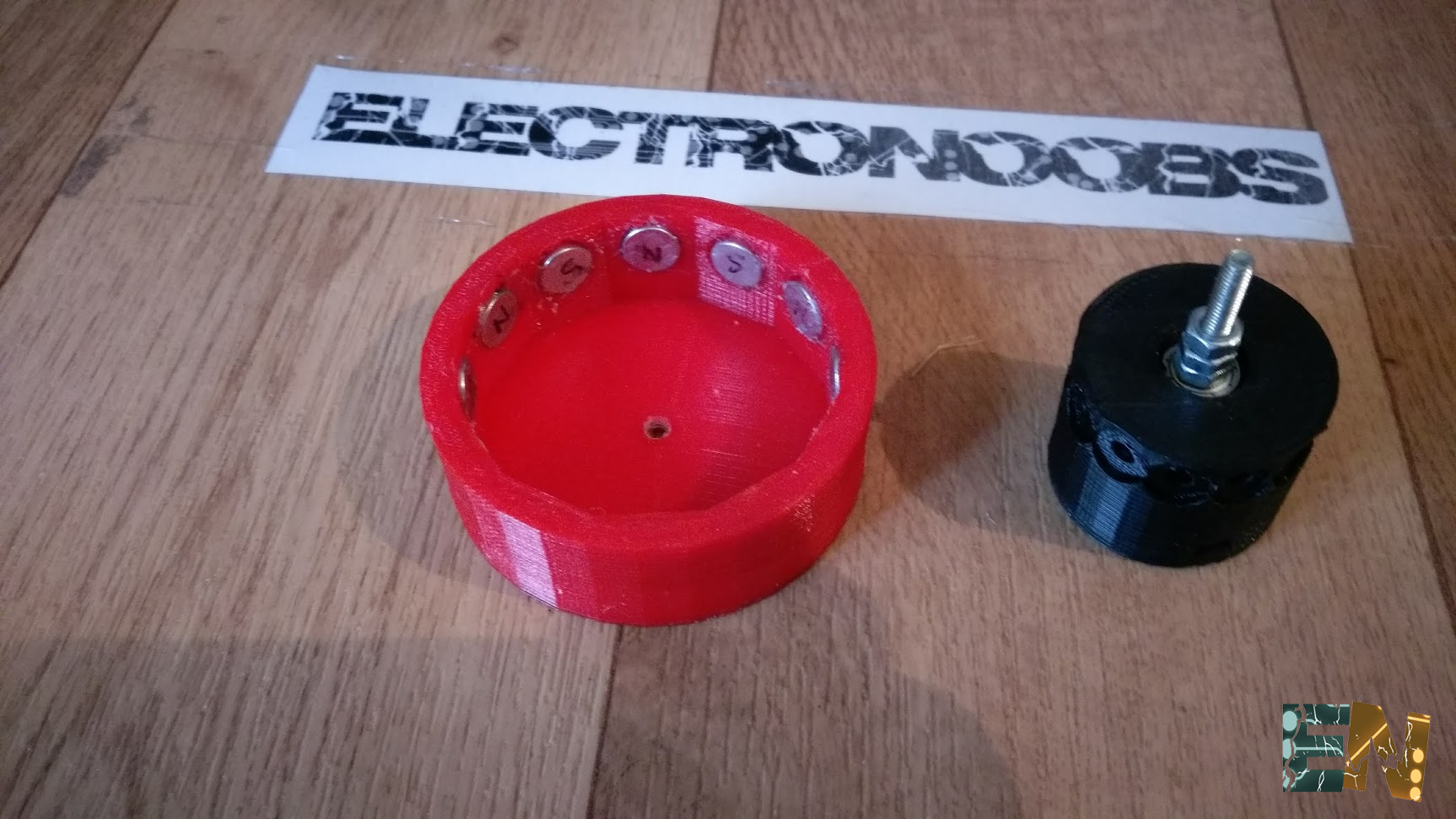
Now we tahe the interior part and add one 10x4mm beatting on the bottom side and one to the top part. We use a M5 5cm long screw as a shaft.
 >
>
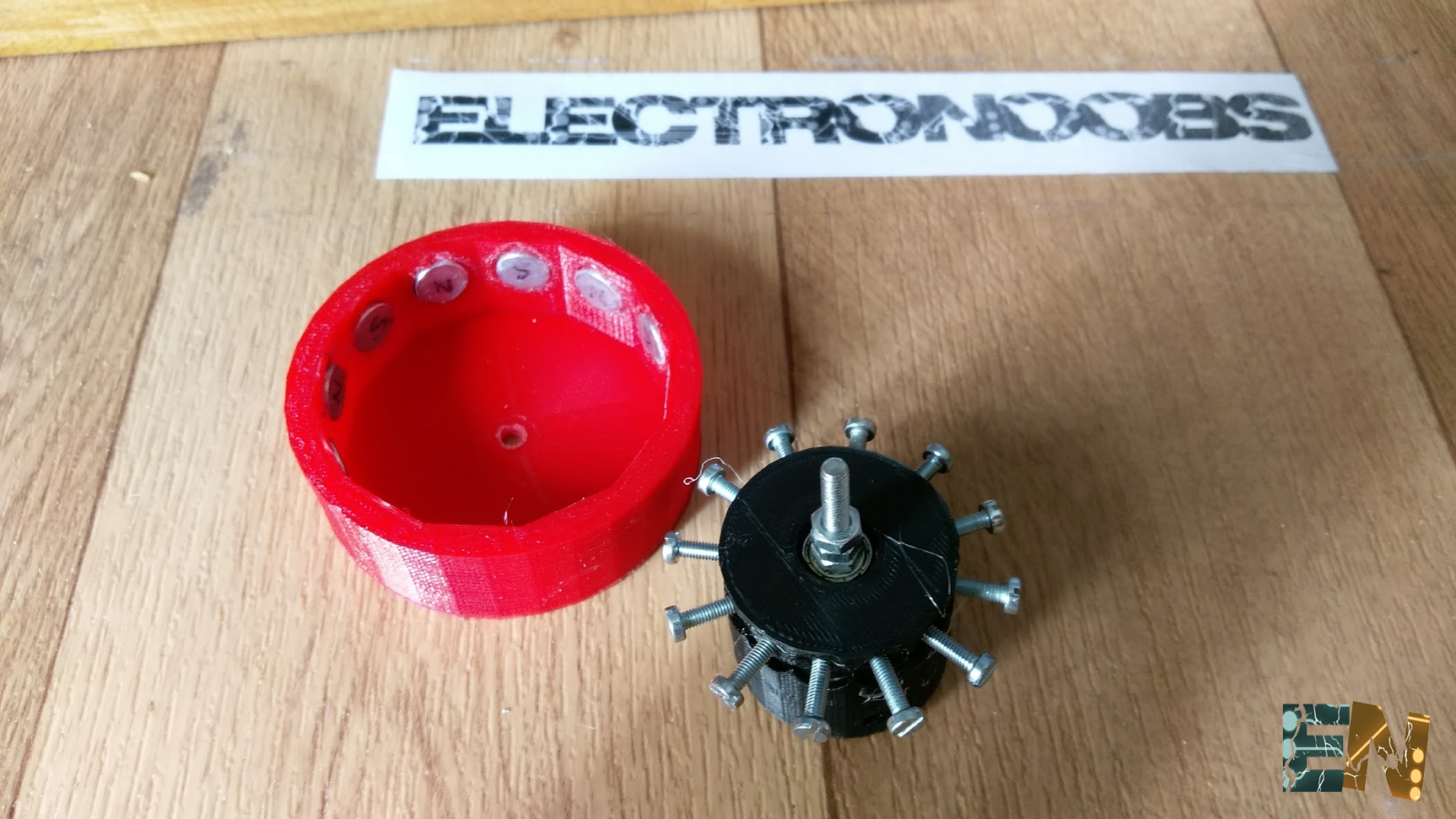
Finally we add 12 M3 18mm long screw in each hole and glue them.
 >
>
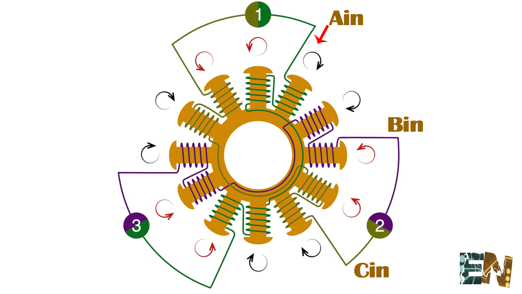
Now we have to make the windings for our motor. We will use dLRK winding type for this 12poles 14 magnets brushless motor. Follow the next schematic to wind your coils.
 >
>
Remember to mark the beginning of each wire with Ain, Bin, Cin adn the final with Aout, Bout and Cout in order to not mix them up. Just stick a smal lable to the wire. We will make 60 turns coils wit a 0.2mm copper wire. Once the winding is complete solder togheter Ain with Cout, Bin with Cin and Aout with Bout. Now just close the motor and screw it up and we are ready to go. Connect the 3 terminals to an ESC and give it a test. You can always adjust things to obtain better results. Change the winding turns, pole to magnet distance, size, etc..
See more tutorials:

 About me
  History
  Let's learn
  Contact us
  Arduino tutorials
 Circuits tutorials
  Robotics tutorials
 Q&A
Q&A Blog
Blog  Arduino
  Circuits
 Robotics
  Modules
  Gadgets
  Printers
  Materials
  3D objects
  3D edit
  Donate
  Reviews
  Advertising