Today we try a circuit from the internet for charging batteries, a BMS or battery management system. I’ll show you a schematic for only one cell and scale it up for any amount of batteries if you want a 2S battery pack, 3S, and so on. The function of this circuit is to charge the batteries, protect them for overvoltage, limit the current and also balance the batteries in case of more than one cell. Is not the best circuit or the most compact, but does it work? Well, stick till the end to find out. I’ll show to the components we need and what each part will do in the circuit and by that, how the circuit works. We mount it on a PCB and test it out to charge and balance our batteries. This circuit is not my idea, there are already a lot of similar circuits on the internet such as this one. So guys, let’s get started.
What’s up my friends, welcome back. This below the PCB we will analyze today and learn how it works. Will this simple circuit be able to limit the current, control for overvoltage and balance the battery pack? Well, let’s see. Lithium ion or LiPo batteries are verry popular, especially with makers like us for small robots, portable devices, RC toy cars and drones and so on. But these batteries are also very sensible and dangerous. If you don’t control the process of charging and discharging of such batteries, they will stop working or worse. The battery cells can swell and even explode from overcharging, and a deep discharge can make the battery fail.
That’s why these batteries should go together with a battery management system unit or BMS. This will control the voltage and current from the battery and keep them safe. Usually, the nominal voltage of a LIPO battery is 3.8 volts and 4.2V when fully charged. So, as soon as the battery cell will reach this value, the charging process should stop and that’s what this circuit should do.
When you have only one cell, you only care about the maximum voltage and the current limit to protect the battery. But when you have a battery pack of more than 1 cell, so 2S, 3S and so on, you also need to balance the value of each individual cell.
We have a PNP transistor connected in series with 4 diodes that will simulate a load. At the base of the transistor, we have a ZENNER reference diode (TL431) which will get open at a certain voltage value and by that connects ground to the transistors base and when the transistor is active, we bypass the battery and waste the power on the diodes instead. This ZENNER diode is the TL431 and it has a reference pin, so by adjusting the potentiometer we can set this reference to be at 4.2V, that’s how we select when the charging process will stop.

So as you can see, this circuit is not that efficient since we waste power inside the diodes and transistor. Also, if the power waste is too high, maybe the transistor would need a heat dissipator so it won’t burn out. But we are not looking for efficiency with this circuit because we can use this charger with a supply from the main outlet so we don’t care that much about efficiency.
We also add a LM317 regulator at the input place in current mode. In this configuration, the current limit is set by the resistor at the output and is equal to a formula, VREF divided by the resistance value. VREF for the LM317 is 1.25V so is should be easy to select a resistor and limit the charging current at let’s say 600mA. We add a second LM317 regulator but on voltage control mode. Without this, the input must be exactly 4.2V. But sometimes we only have 5V from a USB connector or maybe 12V input from a DC adaptor. So, using this second LM317, we can adjust the output to 4.2V so no matter the input value, the voltage that goes to the battery is 4.2V. The output value is given by these 2 resistors.
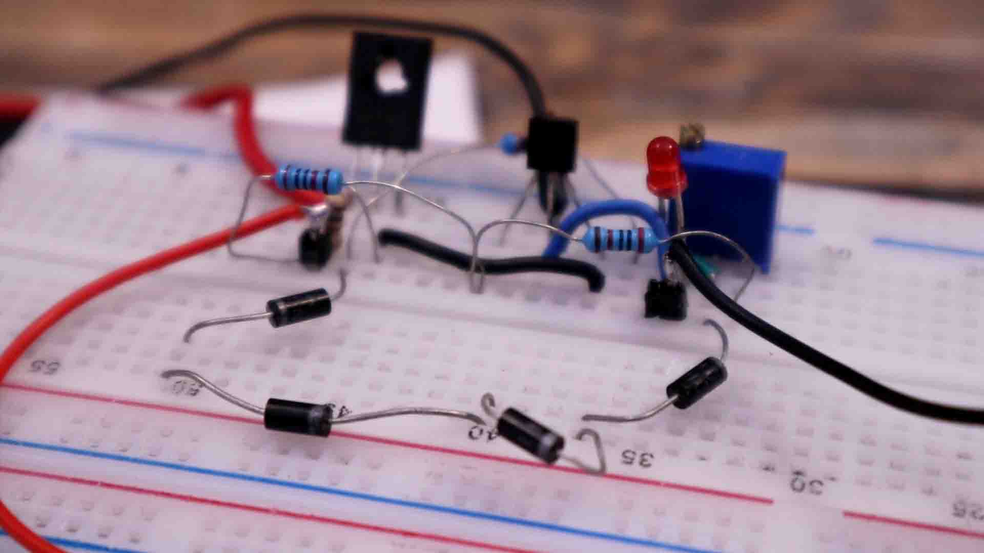
I mount this simple circuit on my breadboard. I supply it with 4.2V from my power supply. I connect my multimeter at the output and using the potentiometer, we first fix the threshold value to around 4.16V, some value below 4.2V. I will use a battery which is discharged and below 4.2V (it was 3.8V). When I connect it to the charger, the LED is turned off. We have a current flow of around 450 mA and the battery is getting charged up. After some time, when we get above 4.16V the LED will turn ON so the charging process is complete. Current is now flowing through the diodes and transistor and we skip the battery, so the cell is protected for over voltage. I measure tge battery and it is 4.11 volts. Ok, but now, how can we control the current limit, which is also an important protection factor? At this point, we can’t really regulate the current limit with this circuit.
Now comes the interesting part. We can take this simple circuit and merge it in series other identical circuits. Now we can charge a 2S battery pack, 3S or more, and also balance the voltage as I mentioned before. With this circuit, we can charge a 3S battery for example and all individual cells will stop charging at 4.2V. Also, by having the two LM317 regulators at the input we have current limit protection but we are also able to supply the entire circuit with let’s say 16 to 20V and set the voltage that goes to the battery to 12.6V, which is the charged voltage of 3 batteries in series.
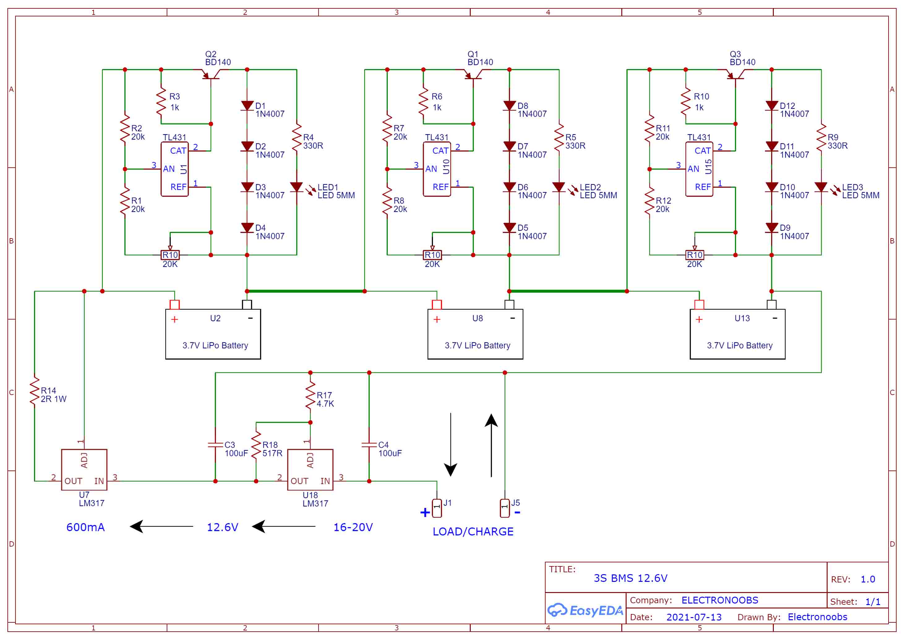
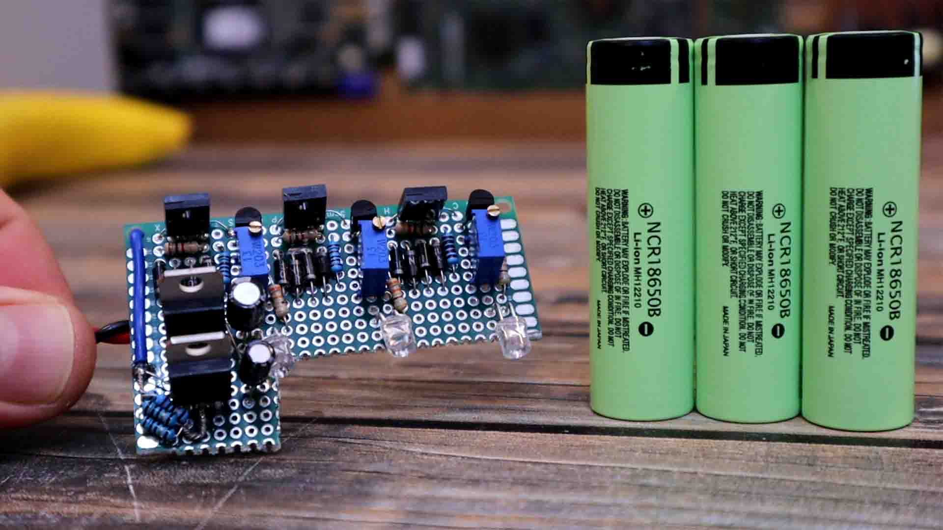
The part list is the same as for 1S but 3 times the same components without counting thw LM317 which we only need 2. Get this final schematic from above. I get all the needed components and solder the circuit on a prototyping PCB. I first add the transistors and ZENNER diodes, then the potentiometers and 4 normal diodes for each group. Then I add the LEDs and finally I add the LM317 regulators and the current limiting resistor made out of 5 resistors of 10 ohms. I make connections with solder and wires on the back. Now we have 3 pairs of connections for the battery and two wires for the input and output. Each LED will turn ON when each individual cell is full. Using the potentiometer, you can fine adjust the threshold value. Changing this resistor connected to the second LM317, can change the charging current limit.
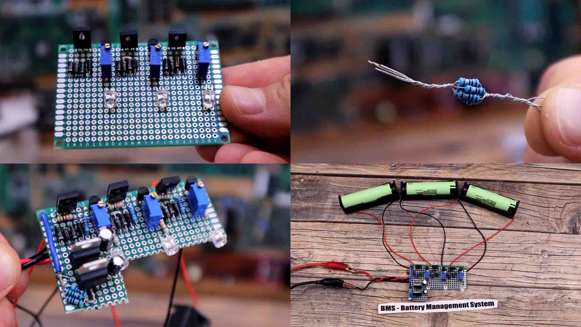
I connect everything and power the circuit with 16V from my power supply. All batteries are now charging. After a while, one LED turned ON almost when we reach maximum voltage. Then the second LED turns ON and finally all 3 are ON, so all batteries are full at almost 12.6 volts. I check the voltage with the multimeter and just below 4.2V. So the circuit works with no problems. The only downside, is the efficiency and heat dissipation. But if you don’t care about that, this circuit could be useful for your battery pack. And if you want more power, you should use powerful transistors, bigger diodes to simulate the load and also add heat dissipator on the components. You should also change current limiting resistor value and power, so get a bigger one.
I hope that you like this vide and that you have learned something new. Now you could make your own BMS circuit and the components are very cheap. The total cost of this PCB is under a dollar if you buy bags of 50 components for just a few cents.
I hope you like this tutorial and maybe you have learned something new. If my videos help you, consider supporting my work on my PATREON or a donation on my PayPal. Thanks again and see you later guys.