
 About me
  History
  Let's learn
  Contact us
  Arduino tutorials
 Circuits tutorials
  Robotics tutorials
 Q&A
Q&A Blog
Blog  Arduino
  Circuits
 Robotics
  Modules
  Gadgets
  Printers
  Materials
  3D objects
  3D edit
  Donate
  Reviews
  Advertising


ESC - Electronic speed controller Part 2
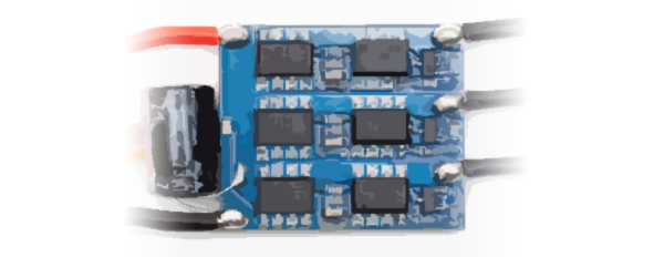
Let's start
We already know what we have to do. Mount the three-phase bridge, connect a microcontroller and read the outputs of BEMF of the motor and create a switch sequence depending on that BEMF read. First of all we create a schematic in Design Spark program. You can use any PCB design program. To make the schematic import all specified components. Make the connections and create the PCB.

It's true, you won't be able to see some of the lines of the schematic so you should download the Design Spark schematic or the high definition schematic in the link below:
HD schematic view:
Anyway we can see 3 controllers (drivers) Dual 2, each connected to two MOSFETs. The controllers inputs are connected to the microcontroller Arduino Nano. The outputs of the three-phase bridge, each with a voltage divider with resistors 1k and 2k connected to the analog input pins of the Arduino. To make the connection of the drivers take a look at the following schematic:

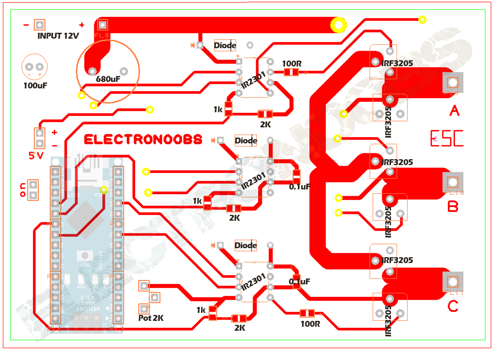
We now have the schematic. Let's create our PCB. Create a two-layer PCB and distribute all components. In the next photo we have the top layer with all the components. I've added all the values for each component. Be carreful while routing.
Now let's take a look at the bottom copper layer. We can see that the through holes are the same. Once again be carreful while routing. Don't make any short circuit. Always check connection with the multimeter beeper.
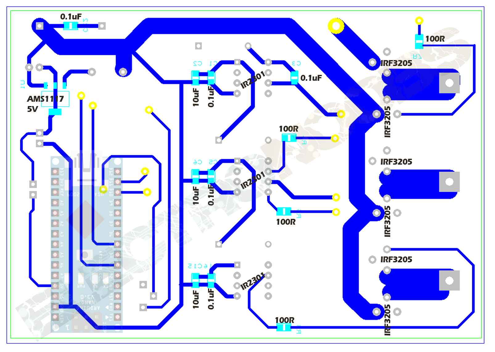
Now let's join together the two layers. I've divided them in order to be able to clearly see each connection. Follow this circuit to mount yours. Maybe print them on a sheet of A4 paper and have them in front of you while solderng.

WE observe the necessary pins for the Arduino to fit in, 12-24 volst input, the (drivers) and 6 MOSFETs. We also note that the main tracks are very thick, 4mm. That's because through them will flow more than 20A of current. The voltage regulator provides stable 5 volts for the arduino. Once we have the PCB, generate gerbers and send them to the CNC milling machine. Such a machine will create a milled double PCB. After (milling) our board looks like this:

We started welding the components one by one. We fill the main tracks with a lot of solder to give them more resistance front a high current.

We have finished our PCB. We connect our Arduino in place and move on to the code part. First we will run a code without detection of the BEMF where simply varying the potentiometer we will vary the motor speed. Without detecting EMF and without the algorithm the motor could stop in every moment and you could notice that it has a very low torque.
We can see that in the code we are not using "delays" because any delay will affect the entire sequence of rotation. We have 6 variables for the states of each transistor of the three-phase bridge. 6 cases will be created to complete a sequence. Then change time between each sequence is given by the analog input from the potentiometer value.
Let's make it more complicate: let's add the EMF read:
Downlaod the
/*http://www.youtube.com/c/ELECTRONOOBS
 * This is the code with EMF detection for the Arduino ESC
 * The speed control is done using a potentiometer connected on pin A0
 * You could always change it in order to have a PWM
 * input signal to control the speed.
 *
 * Please, like, share and subscribe and motivate
  */

int AA1=3;
int AA2=5;
int BB1=11;
int BB2=10;
int CC1=9;
int CC2=6;

int enable=2; //This is not used for now, The ESC is always enabled
int emfA=A0;
int emfB=A1;
int emfC=A2;

int fase=1;
int deltaA=0;
int emA=0;
int sum=0;

int IN=A3;
int Delay=4000;

int it=0;
int it2=1;
static int delta= 0;
static int Lastdelta= -1;

unsigned long previousMillis = 0;

void setup() {
Serial.begin(250000);
  pinMode(AA1,OUTPUT);
  pinMode(AA2,OUTPUT);
  pinMode(BB1,OUTPUT);
  pinMode(BB2,OUTPUT);
  pinMode(CC1,OUTPUT);
  pinMode(CC2,OUTPUT);

  pinMode(enable,OUTPUT);

  pinMode(IN,INPUT);
  pinMode(emfA,INPUT);
  pinMode(emfB,INPUT);
  pinMode(emfC,INPUT);

  //digitalWrite(enable,HIGH);
  //previousMillis = micros();

}

void loop() {


      int emA = analogRead(emfA);
      int emB = analogRead(emfB);
      int emC = analogRead(emfC);
      int sum = (emA+emB+emC)/3;

      unsigned long currentMillis = micros();


  if(currentMillis - previousMillis >= Delay){

      previousMillis += Delay;

  //Phase1 C-B
  switch(fase){
    case 1:
      digitalWrite(AA1,LOW);
      digitalWrite(AA2,LOW);
      digitalWrite(BB1,LOW);
      digitalWrite(CC2,LOW);
      digitalWrite(BB2,HIGH);
      digitalWrite(CC1,HIGH);
      delta = emA-sum;

      break;


  //Phase2 A-B
    case 2:
      digitalWrite(AA2,LOW);
      digitalWrite(BB1,LOW);
      digitalWrite(CC1,LOW);
      digitalWrite(CC2,LOW);
      digitalWrite(AA1,HIGH);
      digitalWrite(BB2,HIGH);
      delta = emC-sum;
      break;

  //Phase3 A-C
    case 3:
      digitalWrite(AA2,LOW);
      digitalWrite(BB1,LOW);
      digitalWrite(BB2,LOW);
      digitalWrite(CC1,LOW);
      digitalWrite(CC2,HIGH);
      digitalWrite(AA1,HIGH);
      delta = emB-sum;
    break;

  //Phase4 B-C
  case 4:
      digitalWrite(AA1,LOW);
      digitalWrite(AA2,LOW);
      digitalWrite(BB2,LOW);
      digitalWrite(CC1,LOW);
      digitalWrite(BB1,HIGH);
      digitalWrite(CC2,HIGH);
      delta = emA-sum;
      break;

  //Phase5 B-A
  case 5:
      digitalWrite(AA1,LOW);
      digitalWrite(BB2,LOW);
      digitalWrite(CC1,LOW);
      digitalWrite(CC2,LOW);
      digitalWrite(AA2,HIGH);
      digitalWrite(BB1,HIGH);
      delta = emC-sum;
      break;

  //Phase6 C-A
  case 6:
      digitalWrite(AA1,LOW);
      digitalWrite(BB1,LOW);
      digitalWrite(BB2,LOW);
      digitalWrite(CC2,LOW);
      digitalWrite(CC1,HIGH);
      digitalWrite(AA2,HIGH);
      delta = emB-sum;
  break;
  }

  if (Lastdelta < 0){
  if (delta > 0)
      {
        Lastdelta=delta; //save the last delta
        fase= fase + 1;
        if (fase > 6) {
          fase = 1;
          }
      }
  }//Zero cross from - to +

  if (Lastdelta > 0){
  if (delta < 0)
      {
        Lastdelta=delta;
        fase= fase + 1;
        if (fase > 6) {
          fase = 1;
          }
      }
  }//Zero cross from + to -

  }//Case ends


  int t =analogRead(IN); //From the potentiometer
  Delay=map(t,0,1024,1,1000); //we obtain the delay speed using the potentiometer
  //we map the values from 1 to 1000 microseaconds


} //loop ends
Upload the code with EMF detection. If we look at the code we see that we need to select the analog pins that will measure the voltage at each terminal, in my case are the pins A2, A3 and A4. The pins that activate the transistors are the same. For the phase change two deltas are created. A current delta and an previous one because we have a phase change depending on the detection of "virtual zero" that can be down from positive to negative or vice versa , up from negative to positive voltages, so thats why we need two deltas . In the Setup we define the pins functionality. In the first loop we measure the voltage on each analog input and make the sum of the 3 measures. This sum will be our "virtual zero" representing the common point of intersection of the three voltages. The delay will be made in the same manner as in the case without emf, by measureing the transcuren microseconds and changing the value of a potentiometer. But the phase shift will come affected by delta values this time. The delta is calculated at each stage and at the end of the code we compare the deltas to detect when we pass through the "virtual zero". It is that the exact time when we should change the phase.

Ask a question on this project on my Q&A page:
See more tutorials: