
 About me
  History
  Let's learn
  Contact us
  Arduino tutorials
 Circuits tutorials
  Robotics tutorials
 Q&A
Q&A Blog
Blog  Arduino
  Circuits
 Robotics
  Modules
  Gadgets
  Printers
  Materials
  3D objects
  3D edit
  Donate
  Reviews
  Advertising


DIY 3bit flash ADC
2.4 Final schematic
We see a straight line of resistors in series. But each pair of these resistors is a voltage divider. The first voltage divider is between R1 and the sum of all the other resistors in series. The second voltage divider is between the sum of R1 and R2 and all the other and so on. So, if each resistor is a 1k resistor we would have this values at the negative input of each comparator depending on the reference voltage applied to the circuit.
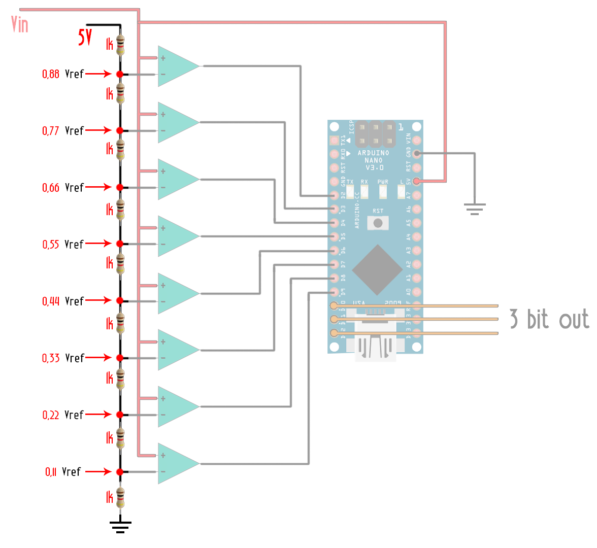
For example, if the reference voltage is 5 volts we will have these values on each of the negative inputs. Now let’s imagine that the analog value that we want to read is 2.5 volts. The first 4 comparators will have a low output since 2.5 is lower than all of those values. But the bottom 4 comparators will have a high output.
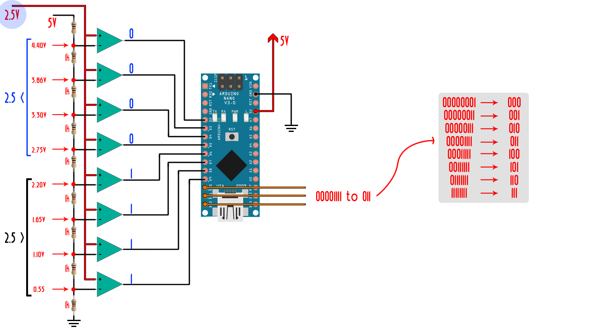
Now is the job of the encoder to pass these 4 ones and 4 zeros to a 3 bits value following this table. If the bottom comparator has a high output and the rest is low we have a 000. If the second and first are high and the rest is low we have a 010 and so on.
As you can see the amount of comparators will give us the resolution. With 8 comparators we have a 3 bit ADC. With 16 comparators a 4 bit converter. With 32 a 5 bit and- so on. The ADC of the Arduino is a 10 bit one so we could have 1024 values for a range of voltages between 0 and 5 volts. That gives us a step of only 4.8mV, which is quite good.
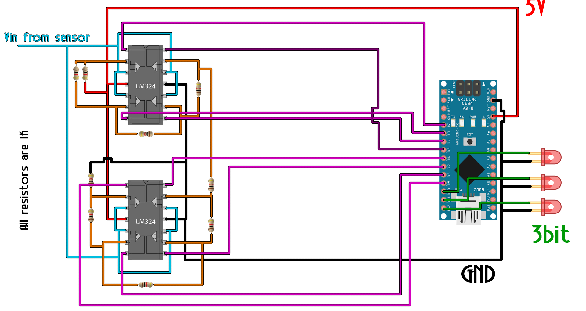
2.5 Build the flash ADC
The ADC that we will build today is a very crappy one. It only has 3 bits. I’ll use 2 LM324 OPAMPs, each with 4 amplifiers. I’ll make the series of voltage dividers with 1k resistors as you can see here on my breadboard from one negative input to the other. The reference voltage will be 5 volts from the Arduino supply. I’ll connect each of the outputs from the comparators to digital pins D2 to D9. Next, I’ll connect 3 LEDs to pin 10, 11 and 12. Those will be our 3 bits of the ADC
I upload this next simple code that will act as an encoder for 8 different values. Depending on which input from the comparators is low, we will turn one or another LED with a total of 3 bits. The input voltage will be the output of this light sensible resistor.
Download the code here:
The input voltage will be the output of the light sensible resistor. I know that the more light it receives, the lower will be its output. Now I get my flashlight closer to the module so the output will be 0 volts so no LED is turned on. I start reducing the light amount and as you can see, now I’ve got 1 bit. I decrease the light amount a bit more and now I’ve got a binary 2. A bit more and now I have a binary 3 and so on with all the values. The resolution of my ADC is between 0.5 and 0.6mV for a reference voltage of 5V. As you can imagine, for a different reference voltage the steps would be different.
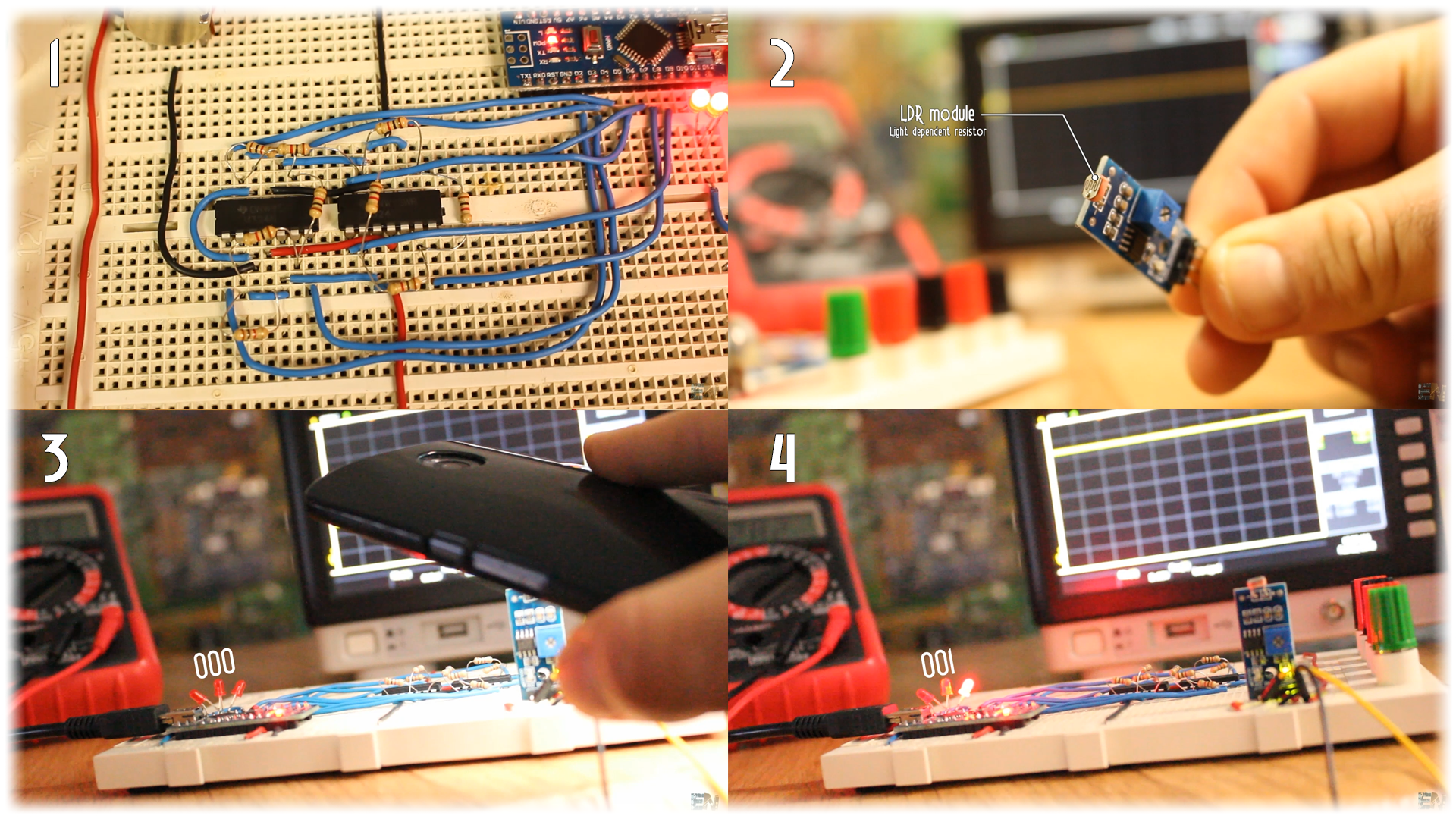
If we follow the table before at 0.5 volts I should have the 000 binary output. At 1.1 I start having the 001. At 1.6 volts the 010. At 2.2volts the 011 and so on.
If we want to sample an analog input with this crappy ADC, we should create a loop inside of the Arduino code with a defined refresh rate and store the values each loop. But I better use the 10 bits ADC that the Arduino NANO already has for that.
Well guys, that’s it for today. Just some basic info about flash ADCs. There are already integrated chips for 8, 10 or 12 bits ADC and those are very cheap.
If you would like to help my projects like this one, I have a Patreon campaign. I would really appreciate that guys.
I hope that you’ve enjoyed this tutorial. If so don’t forget to visit my YouTube channel for more. If you have any question about this video or any other, just leave it on my Q&A page. Also, don’t forget to subscribe and watch all of my other great tutorials. Remember, if you consider helping my projects check my Patreon page as well.