
 About me
  History
  Let's learn
  Contact us
  Arduino tutorials
 Circuits tutorials
  Robotics tutorials
 Q&A
Q&A Blog
Blog  Arduino
  Circuits
 Robotics
  Modules
  Gadgets
  Printers
  Materials
  3D objects
  3D edit
  Donate
  Reviews
  Advertising


DIY inverter
0.0 Basic intro
What’s up my friends welcome back. Today we will look at a very basic circuit but also quite interesting. If you are into electronics I bet that you’ve heard about inverters. We have the rectifiers that pass AC voltage to DC voltage and then we have the inverters that will pass DC voltage to AC. A power inverter, or inverter, is an electronic device or circuitry that changes direct current (DC) to alternating current (AC). The input voltage, output voltage and frequency, and overall power handling depend on the design of the specific device or circuitry. The inverter does not produce any power; the power is provided by the DC source. A power inverter can be entirely electronic or may be a combination of mechanical effects (such as a rotary apparatus) and electronic circuitry. Static inverters do not use moving parts in the conversion process.
So today we will see how an inverter works and how to get the AC voltage output from a 12V battery. So, for example, if you are inside your car and you need 220V to charge your laptop, this will be a very useful circuit since it will give you 220V AC from 12V DC.
So let’s get started.
1.0 What do we need?
I will talk a bit about all the components. You ahve a photo below with some of the components. For more details go to the page of the full part list. There you will find all the components, prices and different options.
See the full part list here:
What’s up my friends, welcome back. Months back I’ve bought the inverter below from a local store. Let’s open it and see what’s inside. As I’ve guessed we have a transformer and some MOSFETS. I apply 12V to the input as the voltage of a car battery and I connect the oscilloscope to the output. As expected I have a 220V and 60 hertz AC output and also as expected, is not a perfect sinusoidal wave as usual home outlet output will give you. That means that some square wave switching is going on here, so, I decided to try my own inverter project so I’ve tried some circuits that I’ve found on the internet. Let’s put this aside and start the tutorial.

1.0 Arduino Inverter
First, I’ll explain you how a basic inverter works. Then we will simulate the circuit with the Arduino and finally make it permanent with a 555 timer circuit.
Before we start, be advised. Even this circuit will be low power, it will still be high voltage that could hurt you. So, if you are not sure about something or not using proper tools, don’t power the circuit. Double check the connections before you apply power and never, never, touch the AC output. I already did that for you so you don’t have to do it. The pain is insane.
So, let’s see how the inverter works. We will study a basic inverter circuit with only two switches, in this case two N channel MOSFETS, so the output won’t be a perfect sinusoidal AC voltage as the home outlet will give you but more like a square wave. So, don’t use this inverter with high tech electronics that would need a perfect sine wave. This circuit is useful for mobile and laptops chargers, low power light bulbs and so on, both because it is low power but also for not having a perfect sinusoidal output.
So, we have a 12V dc voltage on one side and we want an oscillating 220 volts and also 60 hertz at the output. For that we will use a transformer like the one above with one coil on the output side and another at the input, but the coil at the input is divided in half in such a way that the middle pin will be the main input and then we have two outputs.
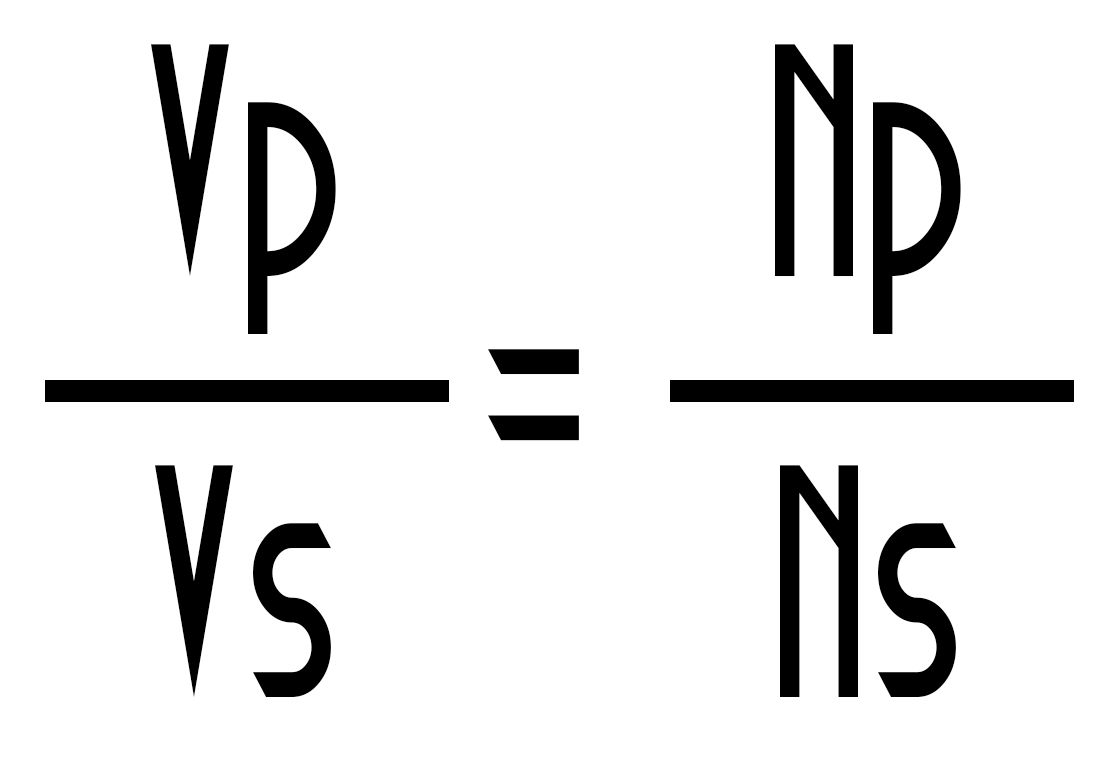
So, let’s imagine now that at each output we add a switch as a push button connected do ground and the middle pin is connected to 12V. If we close the top switch a current will pass only through the first primary coil. So, a magnetic flux is induced in one direction. The core of the transformer will pass that magnetic flux to the secondary coil and as we all know the output voltage of the transformer will be given by this formula below where N is the amount of turns of each coil.
But we also know that transformers won’t work with DC voltages so a current will be induced at the output only on magnetic flux change.
A static magnetic flux like this one that we apply right now won’t induce current in the coil. Only at the beginning when the button is pressed a current will be induced in the coil for a short period of time.W So, we will definitely have to close and open the switch in order to achive an AC voltage at the output. So, turning this two switches on and off one inverted to the other will create a nice oscillating magnetic flux inside the transformer core. That magnetic flux will induce a current in the secondary coil as the faraday law say. So if we have a current passing, we have a voltage drop.
Using the formula above, we can know the amount of turns for each coil. We know that the input will be 12V from a battery and let’s make the primary coil 100 turns. If we want 220 at the output we will need a secondary of 1833 turns.
1.1 The schematic
And that’s it. All we have to do is to fast toggle these two switches in order to obtain the AC voltage using the transformer. How fast you say? Well usually home outlet voltage is between 50 and 60 hertz. That means that we have to turn on and off each switch around 120 times per second and obtain a frequency of 60 hertz.
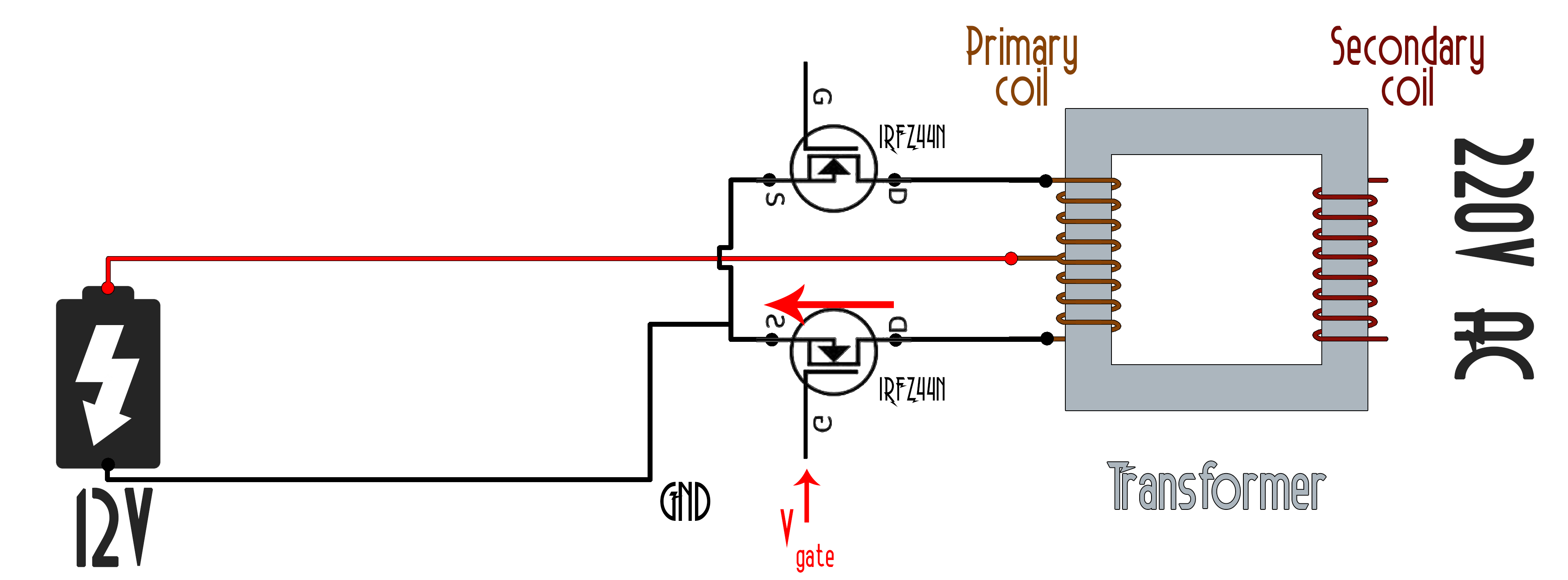
Ok, so of course that the circuit won’t have this kind of switches. Instead we will use MOSFETs. Apply a voltage at it’s gate and it will be activated as a switch allowing current to pass from the drain to the source, in case of this IRFZ44 N channel MOSFET.
For the first test we will use the Arduino to apply the square signal at the gate of each MOSFET. We know that the two signals have to be inverted one to each other so when one is high the other one is low and vice-versa.
We also know that the MOSFETS will work at 12 volts but the Arduino works at with 5V. So, if we want to also apply 12V at the MOSFET gate we will have to use a MOSFET driver. The most basic MOSFET driver will be in this case a BJT NPN transistor like the one in the schematic at the gate of each MOSFET. The pullup resistor is connected to 12V so when the NPN (BC547) transistor is off the voltage at the gate will be 12V. But when we activate the NPN transistor the voltage will drop to ground. So that easy we could obtain a square wave with values from 0 to 12 volts and apply it to the MOSFET gate.
1.2 Test
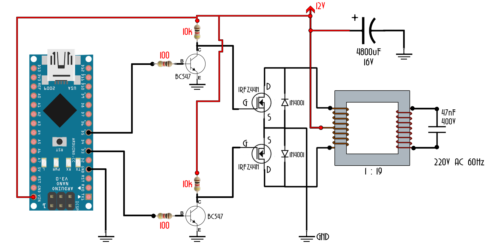
I’ll mount this next schematic to one of my breadboards for tests. Connect the base of the two NPN transistors to pins 3 and 5 from the Arduino with a 100 ohms resistor to each. Remember to share ground between the Arduino and the circuit.

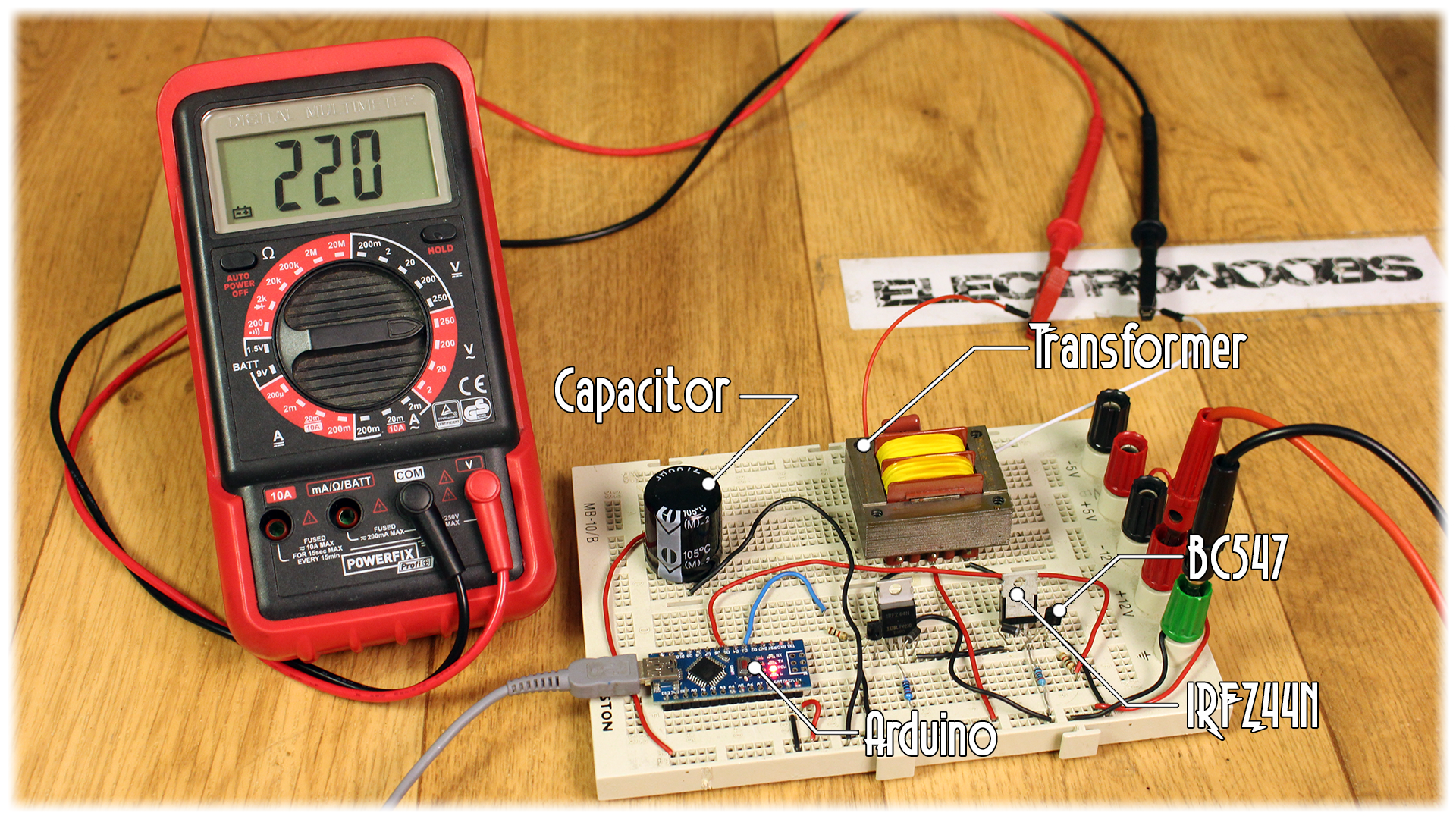
There you have it. The two IRFz44 N channel MOSFETs, the BJT drivers with the pullups to 12 volts, the transformer, a big input capacity to make sure we have a stable input, the Arduino here and a 400V capacitor at the output to smooth the square signal. I upload the next small code to the Arduino. As we can see we have two pins, digital pin 3 and 5 defined as outputs. I set to high one pin and to low the other and after 8ms I do the opposite and add another 8 ms delay. That will give me a 62 hertz square signal on those pins as we can see here on my oscilloscope.
See the example code here:
I’ve got my transformer from old 12V chargers that I had in my workshop. You could wind your own transformer if you want. Since you would probably want to carry this circuit in your car you would want to use small transformers, but in my case, for this example, I have a big one and also with metal core. For higher efficiency try to use ferrite core.
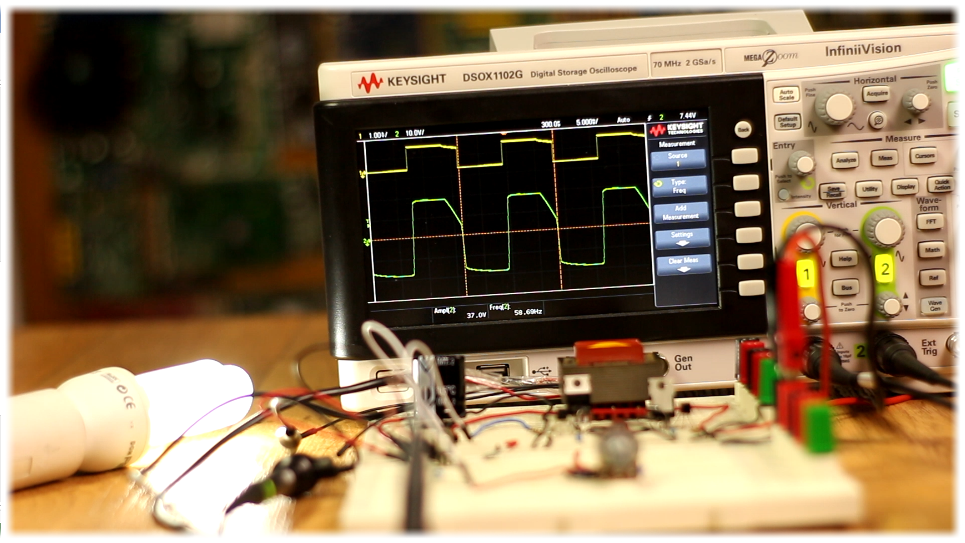
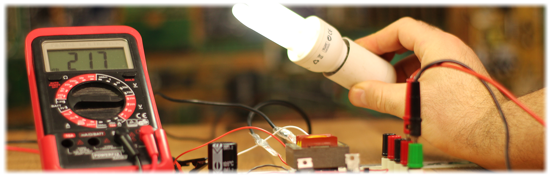
Any way, I’ve made all the connections, uploaded the code, and connected a 15W florescent light bulb at the output. This light bulb requires a 220V and 60 hertz voltage so let’s see if our circuit works. I apply 12V to the input and there you go. The light turn’s on with no problems. I’ll connect the oscilloscope to the output and we can see a 220V peak to peak output. So, the inverter works.
By the way, this is a very low power inverter. I’ve tried higher power light bulbs and it didn’t work. I’ve measured the resistance of the primary coil of the transformer and it is around 6 ohms, so applying 12V to that coil, there will be around 2 amps of current passing. So 12V times 2Amps is equal to a input power of around 24W. Of course, this is the ideal power. I haven’t calculate the real power for this circuit.
Ok so, using the Arduino wouldn’t be that efficient. In this example I’ve powered the Arduino with the USB cable but in a real inverter I should also supply it from the battery. And that would draw the battery even faster since the Arduino is using lineal voltage regulator for 5 and 3.3 volts which are not efficient at all. So how to create our square signal without the Arduino?