
 About me
  History
  Let's learn
  Contact us
  Arduino tutorials
 Circuits tutorials
  Robotics tutorials
 Q&A
Q&A Blog
Blog  Arduino
  Circuits
 Robotics
  Modules
  Gadgets
  Printers
  Materials
  3D objects
  3D edit
  Donate
  Reviews
  Advertising


DIY power suppy
Step 3 - Input and output
Now that the module is prepared with the bigger potentiometers soldet 2 or 3 yellow wires (12V) to the positive input of the module (IN+) and 2 or 3 wires of GND from the PC source to the negative input of the module (IN-). Solder the positive output (OUT+) to the red wire of the voltmeter module and at the same time to a toggle switch as in the schematic. The other pin of the switch to the main red bannana plug output. Solder the negative output (OUT-) to the black wire of the voltmeter display and the blue wire from the display to the black bannana plug output.
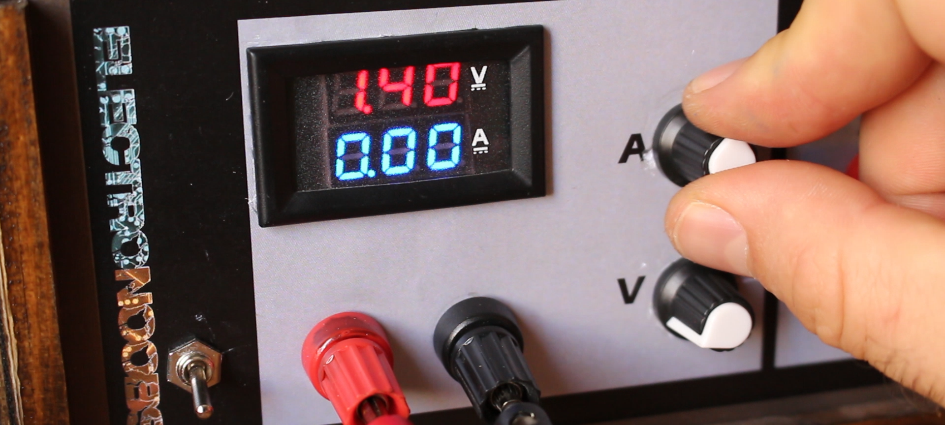
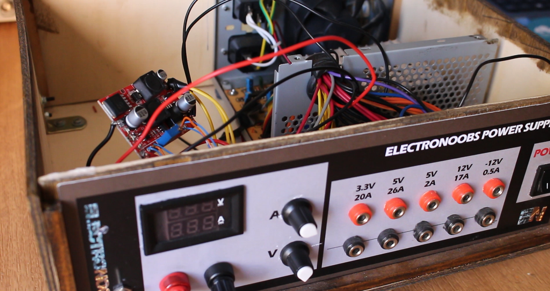
Finally you should connect 5V (red wire from the PC source) to the thin red wire of the voltmeter display in order to supply the internal electronics and the 7 segments light. The circuit is ready. As an extra I've connected separate banana plugs for each of the other fixed outputs of 3.3, 5 and 12 volts.
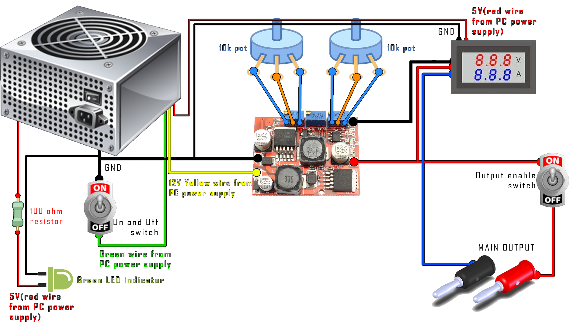
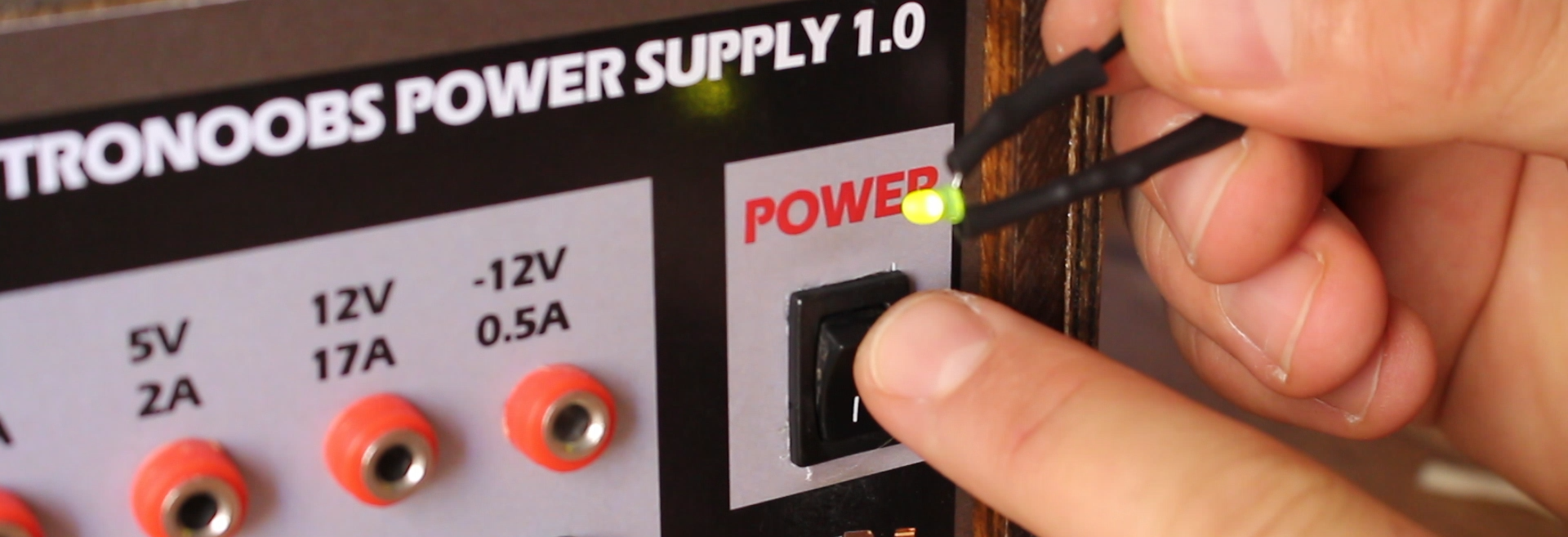
Now, as an extra, solder a 100 ohms resistor to a red wire (5V) and solder a green LED to it. Also connect GND. This will be a power on indicator light.
Step 4 - Case
I've made my case from balse wood. You could download the plans from the link below if you want to build the same. Remember to add holes for the PC power supply fan and able air to flow. If you want the same front panel label you could also download it from a link below. Just glue it in place befor drilling the holes. Fit everything inside the case, screw in place the connectors, potentiometers and switches, add the display and that's it. If you use a metal case remember to make a connection between the PC power source and your case in order to share earth connection.
Download links
Front panel label:
Scheamtic: