One of the main differences is their channel type. It could be N or P. The main difference between an N-Channel and a P-Channel MOSFET is that N-Channel usually goes to the ground or negative side of the load, and the P-Channel to the VCC or the positive side and that might result into problems when using them in a circuit.
That's why we usually create a so called MOSFET half bridge with a P-MOS on the HIGH side and an N-MOS on the LOW side. But you see, for high current loads, the P-Channel MOSFET could not work ok because its ON resistance is usally a lot higher tnan an N-Channel.

We can see in this picture how with the N-channel we have the laod connected to VCC and the MOSFET is connected with its source to GND. Since the N-channel mosfet will start opening its gate when the votlage at the gate is higher than the voltage and the source, this configuration is perfect because the source voltage will always be 0V. On the other side, we connect the P-channel on VCC and the load on the low side. So what would be the problem if we use the N-channel MOSFET on the high side???
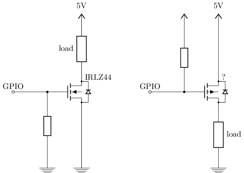
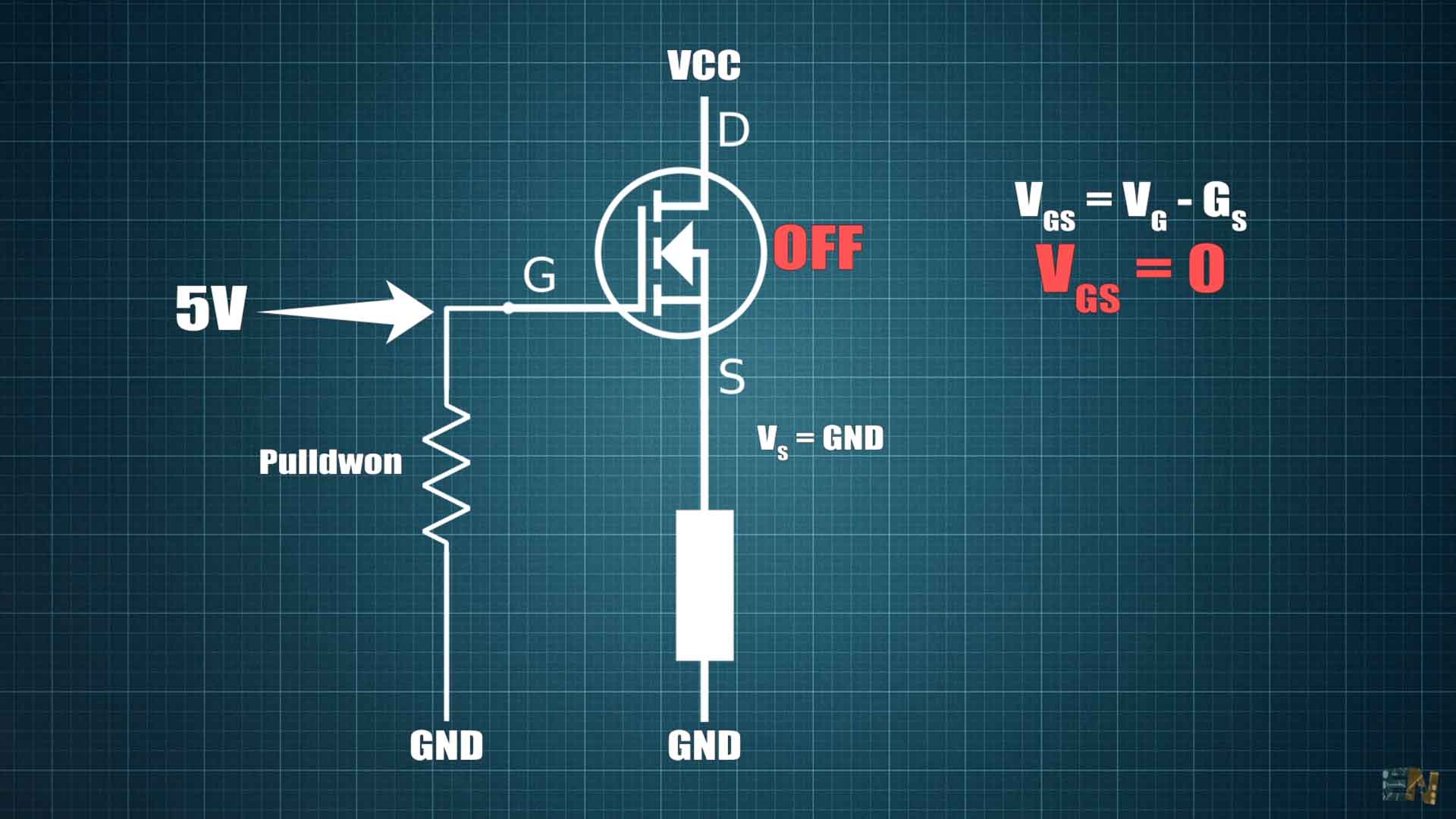
So, instead of using P-MOSFETs for the high side, we sometimes use N-channel MOSFETs as well because they could have ON resistance of only a few milli ohms. But here comes the problem. Now the load is connected at the source of the N channel MOSFET. We add a pulldown to the gate so the MOSFET is in the OFF position so the voltage between the source and the load is 0.
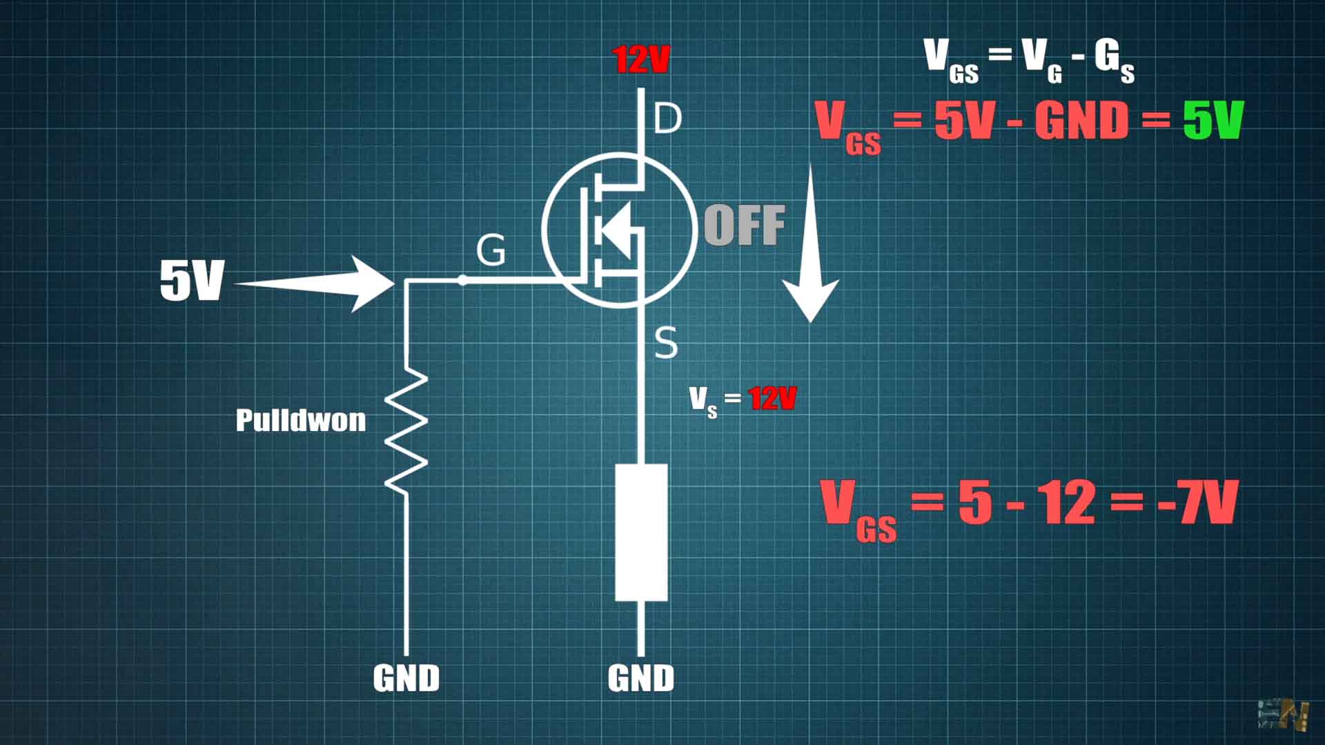
Let’s say is a logic level MOSFET and I apply 5V at the gate, the MOSFET will turn on because the GS voltage is 5 minus 0 equal to 5V. But when the MOSFET turns ON it will also apply VCC to the LOAD so now the voltage at the source is VCC which could be for example 12V. So at this point the GS voltage is 5V minus 12V equal to -7 volts, so the gate voltage is lower than the source voltage so the N-channel MOSFET will be turned OFF. That’s the main problem of this configuration.
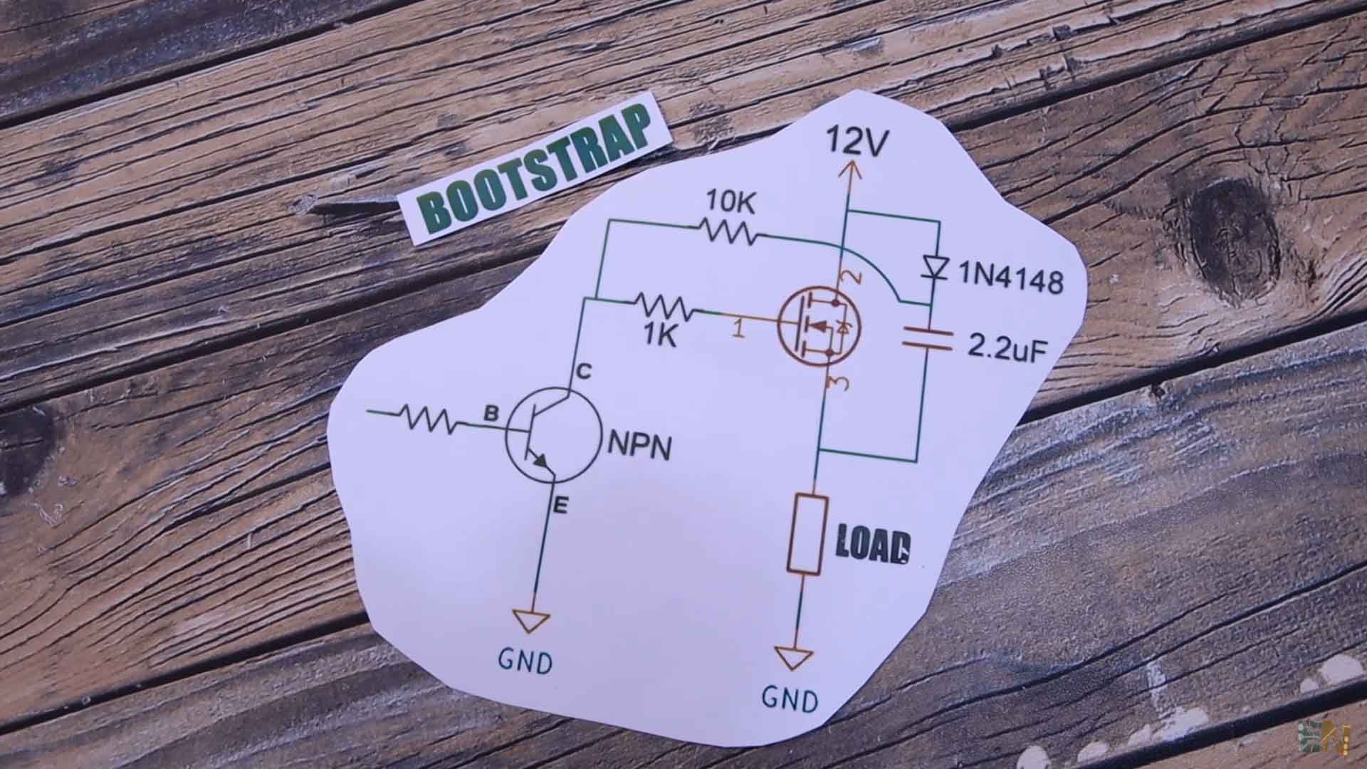
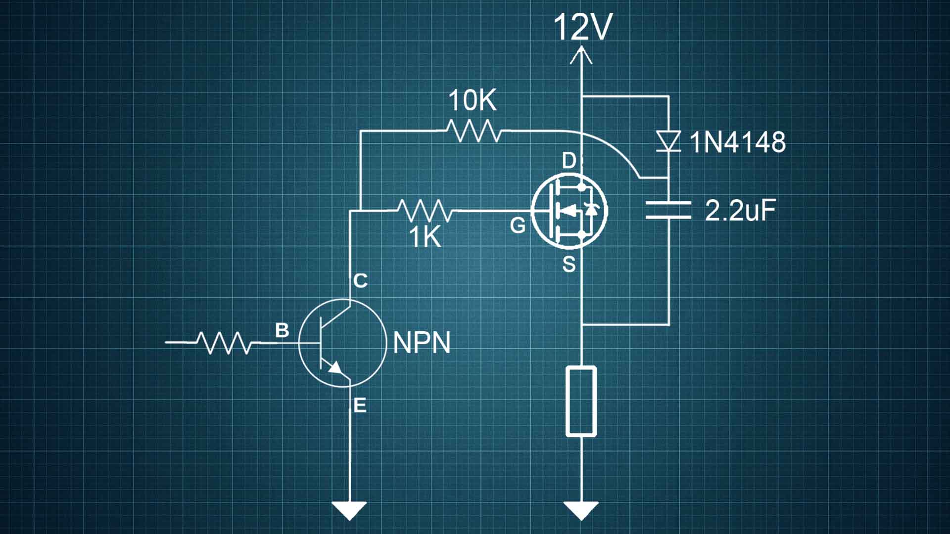
To solve this we use what is called bootstrap. This is the most-simple bootstrap schematic. The N channel MOSFET is connected as before to 12V, the load is below but now we have a diode and a capacitor connected between the drain and the source together with two resistors and a NPN transistor. When the input signal is HIGH, the NPN transistor is ON. That means that the gate of the MOSFET is connected to 0 V so the MOSFET is OFF. But at the same time this capacitor will charge up through this diode. It will charge up at 12V.
So now, when I place a LOW signal at the NPN transistor base, it will turn it OFF. So at this exact moment, the voltage between the source and the gate will be 12V of the capacitor in series with 12V from VCC so 24V. So this time the GS voltage is 24 - 12 equal to 12V so the MOSFET is still ON. That’s what bootstrap is doing, elevating the gate voltage so the gate to source voltage is always higher so the MOSFET is still ON. One thing to have in mind. If the ON and OFF switch process is very slow, the capacitor might have time to discharge through the 10K resistor or leak through the reverse of the diode. In that case the voltage in series won’t be 12V anymore and it might not work for slow switching.