Panel Cookies
yt_link
insta_link
fb_link
twitter_link
Blog#12 - Optic CNC


Last tutorial - homemade soldering iron!
Check here my last tutorial. I hope that you will like it. Keep up you guys!

last tutorial


Optic encoded CNC machine
Help me by sharing this post

Go back ↞ See other blog→

Author: Andrei
15/07/2018
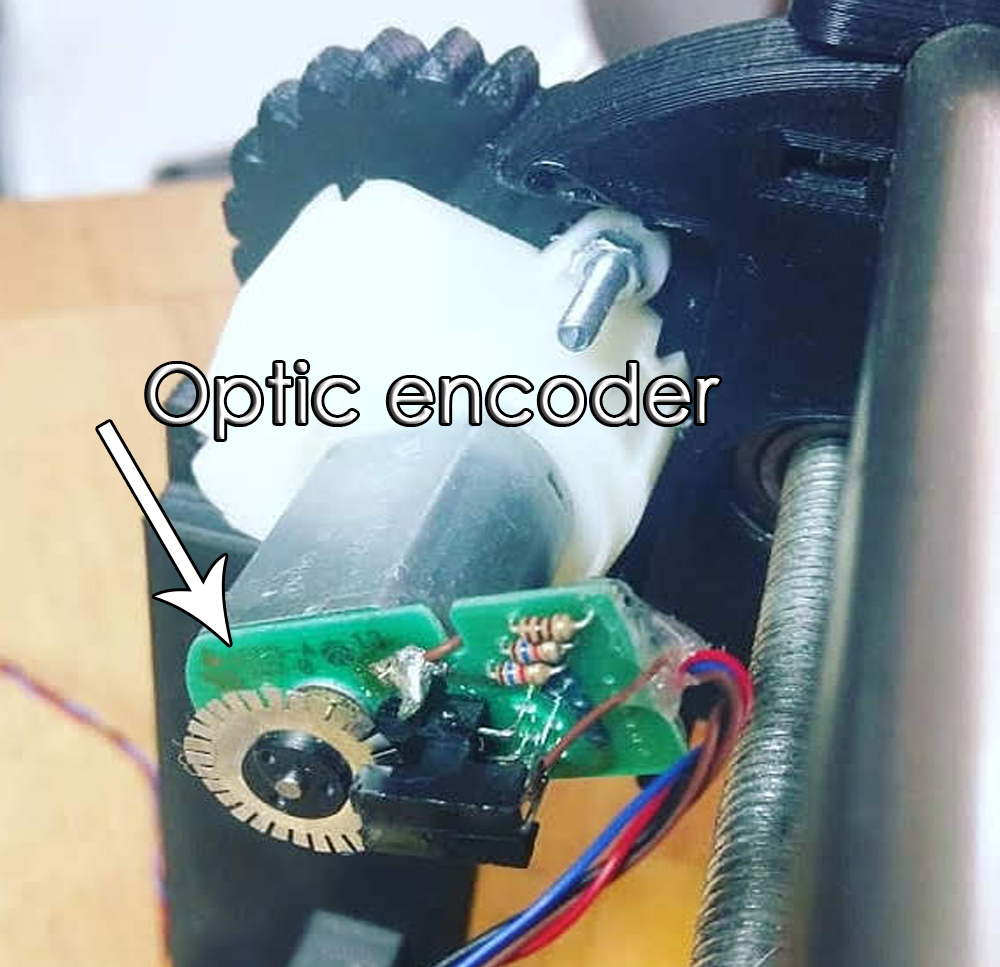
ELECTRONOOBS is working on his optic encoded CNC machine for more than 2 years, yes, it is a very long project. A common CNC machine works with stepper motors. But, in this case, he is using normal brushed DC motors to move the axis. But the advantage of using stepper motors is that you can use them in open loop. You send the amount of steps to make and it will make the steps. You don't have to care about anything more. In case of brushed DC motors, you can't directly control the position of the shaft. For that an encoder is used.

To order your boards, use PCBWay.com and select your color.


There are a few types of encoders. Between lineal an rotary encoders, ELECTRONOOBS went with a rotary encoder placed directly on the DC motor shaft, and to be more specific, an optic IR rotary encoder in quadrature.

An optic sensor detects the holes on the drilled disc placec on the shaft. With that, using boththethe microcontroller is very easy to count steps. Besides, if we use a dulal sensor, both direction and amount of steps could be measured. On the photo we can see the metal drilled disc and the infrared optic sensor. Thtn, the DC motor is connected to the gear system of the CNC machine.


To control the DC motor and H-bridge is used. With this IC we can control both direction and speed. The machine has 3 motors and each IC that EN used could control 2 motors. That's why the final PCB has two of these ICs. The final board also has 5 push buttons for manual control, and LCD to print the coordinates for XYZ and some extra components for voltage regulation, UART communication, etc.
The last part, the UART port, is very important. A CNC machine should work with G-codes. In order to receive the XYZ coordinates, the UART communication is used. A Java platform was created by EN that could be opened on the PC and that will send line by line the G-code coordinates. An external FTDI module is used since the board doesn't have one. That's it for this update. Let's see what will be the next step in ELECTRONOOBs project.


Help me by sharing this post

Go back ↞ See other blog→

ADVERTISERS


PCBWAY PCB service


Curso Arduino Online nivel Intermedio