See the past tutorial about this for more. But it is quite basic. We charge the capacitor using one of the Arduino pins. Then we discharge it through a resistor. The formula tells us that the capacitance value is equal to the time it took to reach 63.2% of the fully charged voltage divided by the resistor value.
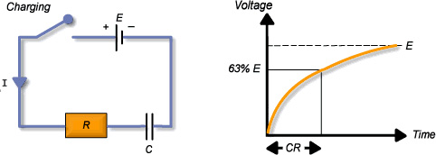
So, in the code, when capacitance mode is selected, we charge the capacitor, discharge it and count time. When the capacitor reaches 63.2% of Vcc, we stop the time counter and calculate the capacitance value using the formula.
For more details see the INDUCTANCE METER TUTORIAL. But an inductor in parallel with a capacitor is called an LC circuit, and it will electronically "ring" like a bell. Well regardless of the frequency or how hard a bell is struck, it will ring at it’s resonating frequency. We will electronically strike the LC bell, wait a bit to let things resonate, then take a measurement. There is some internal resistance so this is really an RLC circuit.
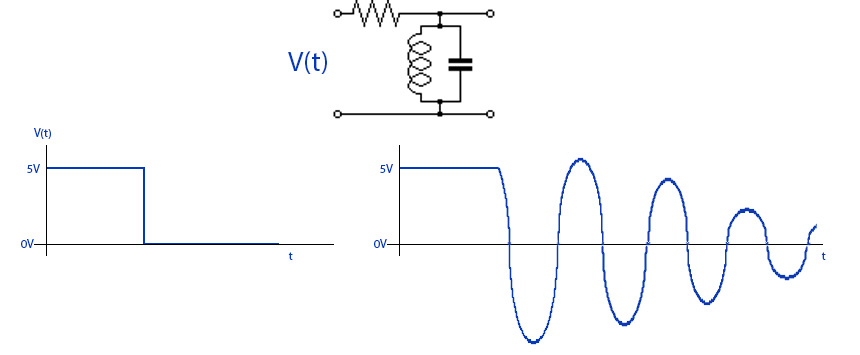
When the multimeter is into inductance mode, we count the time between each pulse of the resonancy frequency. If we know the frequency value and also the used capacitance, in this case 2uF, we can get the inductance value adn print that to the OLED screen.
This part is also simple. We use the ACS712 module to measure current. The ACS712 current sensor is an economical solution for measuring current, it works internally with a Hall effect sensor that detects the magnetic field produced by induction of the current flowing through the line being measured. The sensor gives us a voltage output proportional to the current, depending on the application we can use the ACS712-05A, ACS712-20A or the ACS712-30A, for ranges of 5, 20 or 30 amps respectively
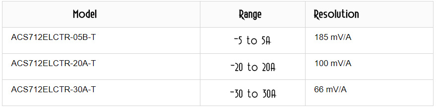
We know the mV / A value for each range so all we haev to do is to measure the voltage drop from the current sensro and divide that by the mV value and we get the current value. Is that easy. But, the sensor gives us a value of 2.5 volts for a current of 0A and thereafter increases proportionally according to the sensitivity, having a linear relationship between the voltage output of the sensor and the current. This relationship is a straight line in a graph Voltage vs Current where the slope is the sensitivity and the intersection in the Y axis is 2.5 volts. The equation of the line would be the following
float resolution=0.185; //in Volts/Amps for a 5A sensor

void setup() {
  Serial.begin(9600);
}

void loop() {

  float SensorVoltage= analogRead(A0)*(5.0 / 1023.0); 	//We read the voltage drop
  float I=(SensorVoltage-2.5)/resolution; 				//We get the current value
  Serial.print("Current: ");
  Serial.println(I,3);
  delay(200);
}
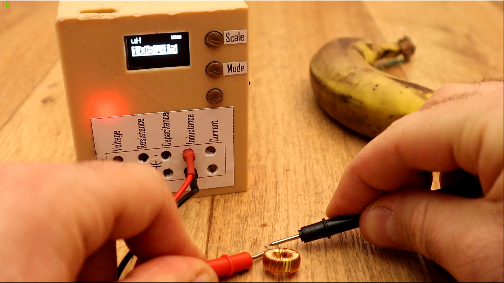
Remember to downlaod the full code. Tune the values at the beginning of the code. Also install the adafruit libraries for the ADS1115 module and the OLED screen. Compile, make the connections and upload. Test the multimeter.
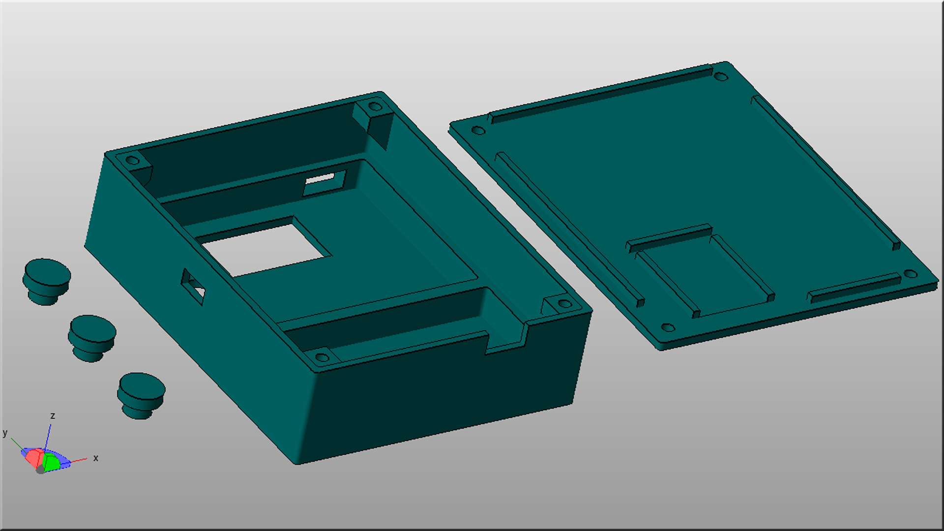
Downlaod the 3D files from below. I've used 2 perimeters, 20% infill and a 0.4mm nozzle and PLA amterial. The case is made out of 2 parts and 3 plastic buttons. Cut your PCB to the case dimensions and place that inside. It has space for the OLED screen, sliding switch and the USB connectors for the Arduino and charging module.