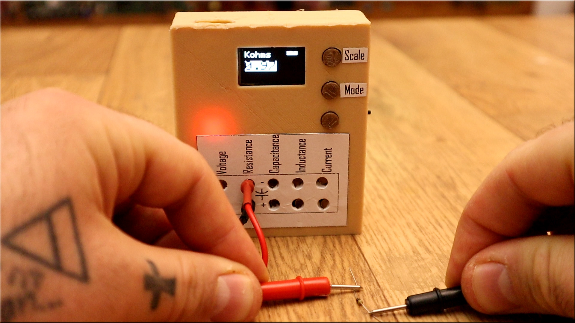
In this tutorial we will merge all the parts seen in these past tutorials here. In those tutorials we have seen how to measure resistance, current, indcutnace and capacitance. Measure voltage is very easy. In this tutorial we make a 5 in 1 multimeter based on an Arduino, an ADC module and an LC tank circuit. The case is 3D printed. You have the schematic, code and all you need to amke this project.
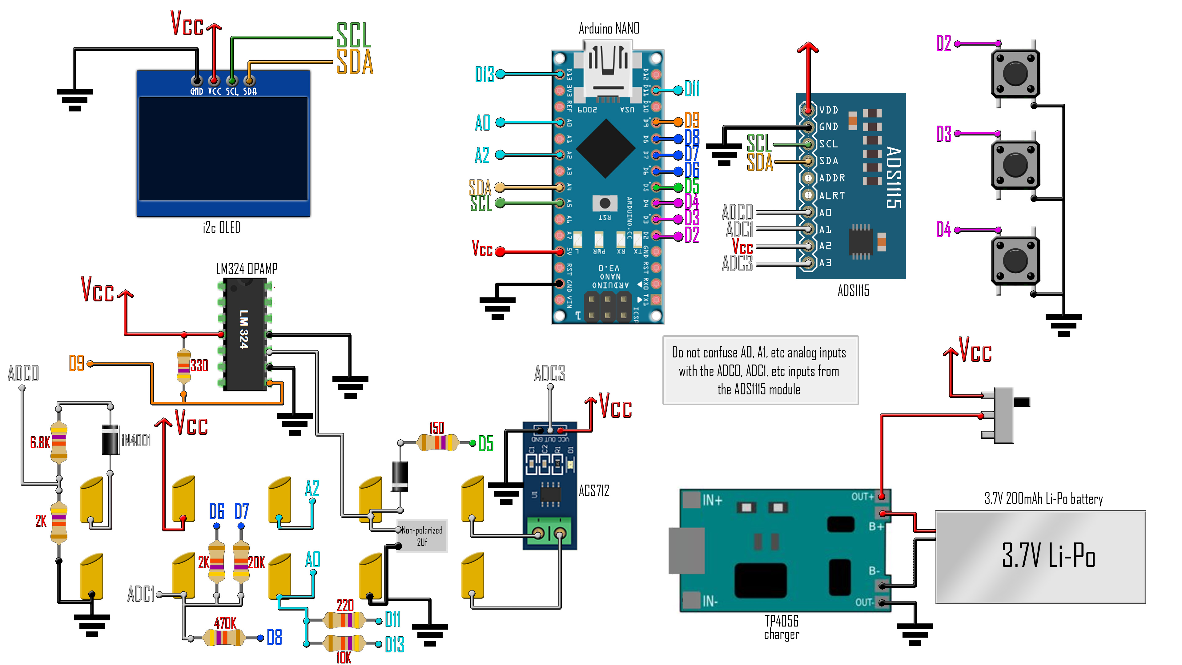
You have the schematic for this project below. You need the Arduino, the ADS1115 ADC module, the OLED display, the ACS712 current module, the TP4056 based charger and a few more components. You have all the values below. After you make the connections, you can downlaod the code and upload it to the Arduino and give it a test.
Below you have the full code for this project. Download it and read it line by line in order to understand it better. You will also need the OLED library and the library for the ADS1115 module so downlaod those and install them on your Arduino IDE.
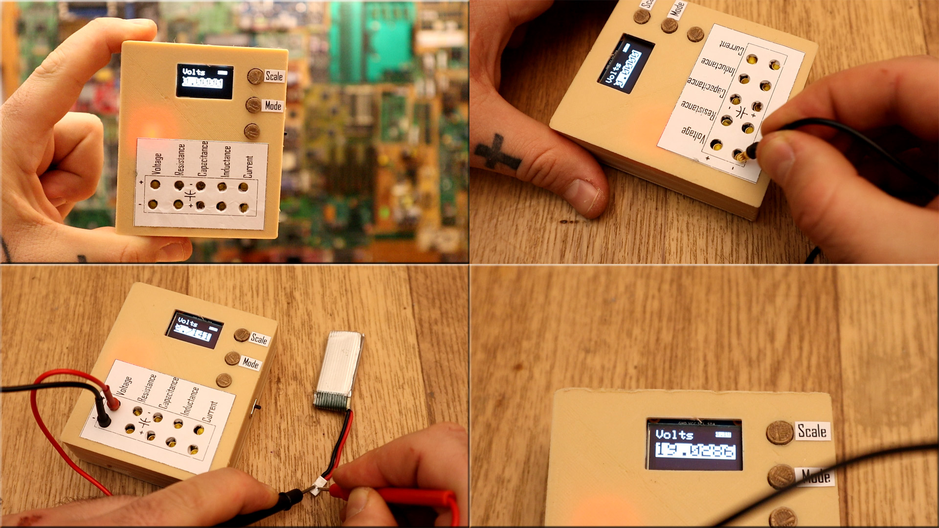
But first, let's go step by step and see how we measure each value: voltage then resistance, then capaciance, inductance and current. Let's start with volage since that is very easy. Below you have an example code for the ADS1115 module using the library. We read and print the values to the serial monitor. The ADS1115 has its own refference so it doesn't matter if the voltage battery is 3.7 or 4.2 or any other value, the output will always be precise.
#include <Wire.h>
#include <Adafruit_ADS1015.h>

Adafruit_ADS1115 ads;
const float multiplier = 0.1875F;

void setup(void)
{
  Serial.begin(9600);
  // Descomentar el que interese
  // ads.setGain(GAIN_TWOTHIRDS);  +/- 6.144V  1 bit = 0.1875mV (default)
  // ads.setGain(GAIN_ONE);        +/- 4.096V  1 bit = 0.125mV
  // ads.setGain(GAIN_TWO);        +/- 2.048V  1 bit = 0.0625mV
  // ads.setGain(GAIN_FOUR);       +/- 1.024V  1 bit = 0.03125mV
  // ads.setGain(GAIN_EIGHT);      +/- 0.512V  1 bit = 0.015625mV
  // ads.setGain(GAIN_SIXTEEN);    +/- 0.256V  1 bit = 0.0078125mV
  ads.begin();
}

void loop(void)
{
  int16_t adc0, adc1, adc2, adc3;
  adc0 = ads.readADC_SingleEnded(0);
  adc1 = ads.readADC_SingleEnded(1);
  adc2 = ads.readADC_SingleEnded(2);
  adc3 = ads.readADC_SingleEnded(3);
  Serial.print("AIN0: "); Serial.println(adc0 * multiplier);
  Serial.print("AIN1: "); Serial.println(adc1 * multiplier);
  Serial.print("AIN2: "); Serial.println(adc2 * multiplier);
  Serial.print("AIN3: "); Serial.println(adc3 * multiplier);
  Serial.println(" ");
  delay(1000);
}
So, make the connections and uplaot it to the Arduino. It will measure voltage with high precision.
For more details see the RESISTANCE METER TUTORIAL. But we will use a basic voltage divider to calculate the resistence. As we know, a voltage divider is made of two resistences (R1 and R2) in series. The output voltage in the middle point is [R2/(R1+R2)]Vin. Using this formula and knowing the value of one of the two resistors and measuring the Vout it is very easy to calculate the resistence of the seacond resistor.
On our schematic, the resistance measurement is made with the 2k, 20K and 470K resistors connected on pins D6, D7 and D8. By that we have 3 different scales. If we set D6 as OUPTUT and set to LOW, that will our GND for the voltage divider. The other pins, D7 and D8 are set to INPUT so they have high impedance. So our volage divider is amde out of the 2K resistor and the unknown resistor. We measure the voltage on the ADC1 pin and using the formula we get the resistance. We do that for all the scales.
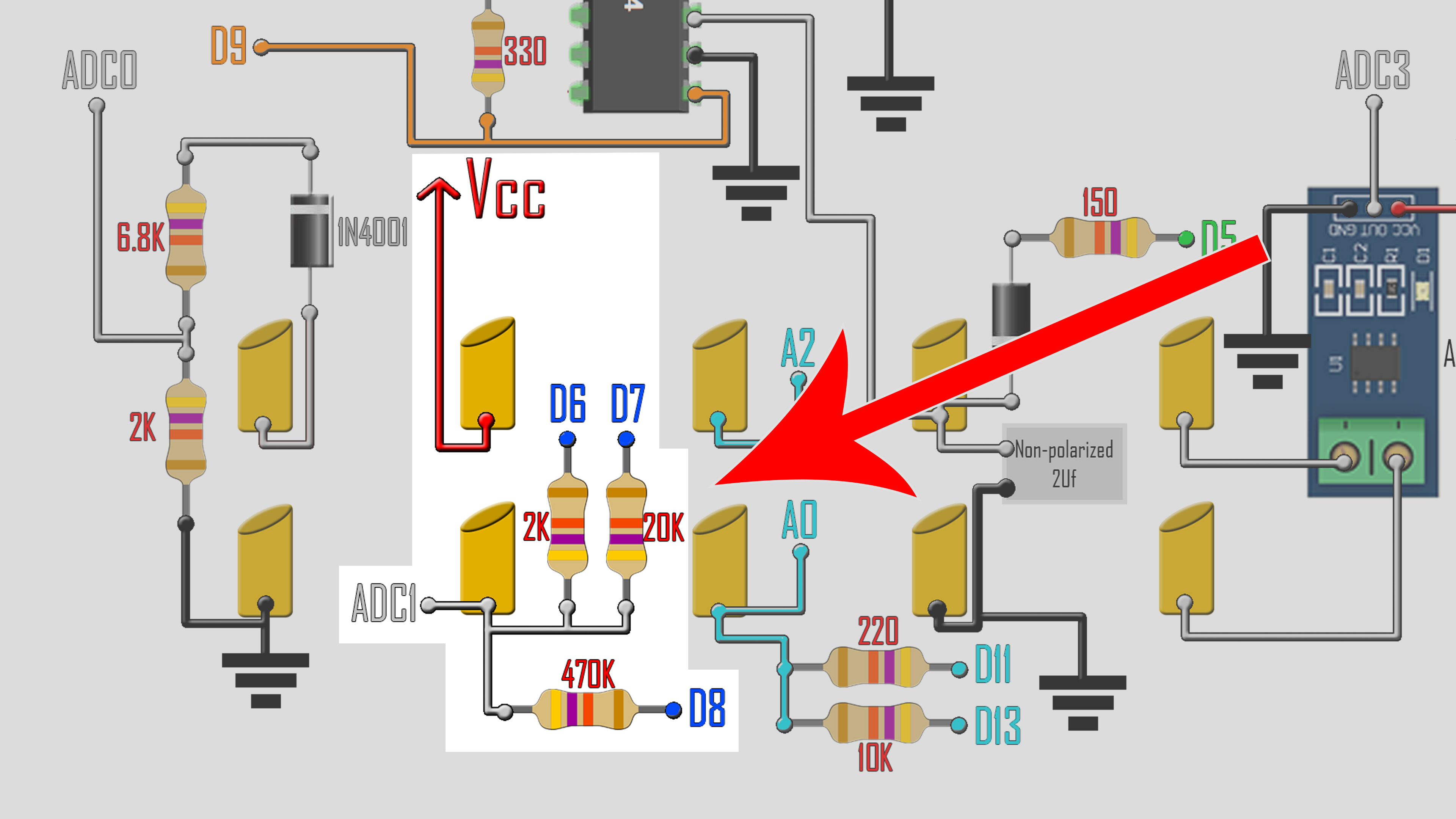
Make sure that you measure the vlues of the 2k, 20K and 470K resistors so you know the exact value and put that later in the full code. Put the multimeter into resistance mode and try different values. Tune your values in the code till you get good results.