In this short tutorial we will see how to mount the circuit, read the signal from the PIR sensor and then control the delay when the Relay will be switched on and by taht the light bulb will be turned on as well. See scheamtic and example code below.
Below we have the schematic for this project. The PIR sensor will give a high signal for 3 seconds when it detects movement. Then we read that signal with the Arduino. At the same time we read the potentiometer value and map the delay between 5 seconds and 60 seconds. You could change that in the code if you want. The Arduino will control a NPN transistor that will activate te relay and by that turn on the light bulb.
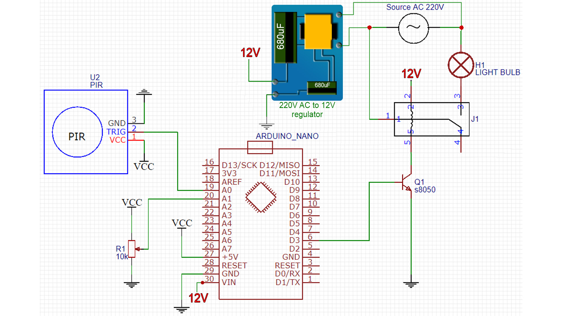
Copy or downlaod the code from below. Make the connections as in the schematic above and then upload the code. The Arduino is supplied with 12V from the 220VAC to 12VDC regulator. Change this line "delay_time = map(analogRead(delay_in),0,1024,5000,60000); " if you want a different delay range than 5 to 60 seconds.
int sensor_in = A0;
int delay_in = A1;
int relay_out = 3;

bool relay_activated = false;
unsigned long delay_time = 5000;

void setup() {
  pinMode(sensor_in,INPUT);
  pinMode(delay_in,INPUT);
  pinMode(relay_out,OUTPUT);
  digitalWrite(relay_out,relay_activated);
}

void loop() {
  delay_time = map(analogRead(delay_in),0,1024,5000,60000);

  if(analogRead(sensor_in) > 500 && !relay_activated)
  {
    relay_activated = true;
    digitalWrite(relay_out,relay_activated);
    delay(delay_time);
  }

  if(analogRead(sensor_in) < 500 && relay_activated)
  {
    relay_activated = false;
    digitalWrite(relay_out,relay_activated);
    delay(10);
  }


}
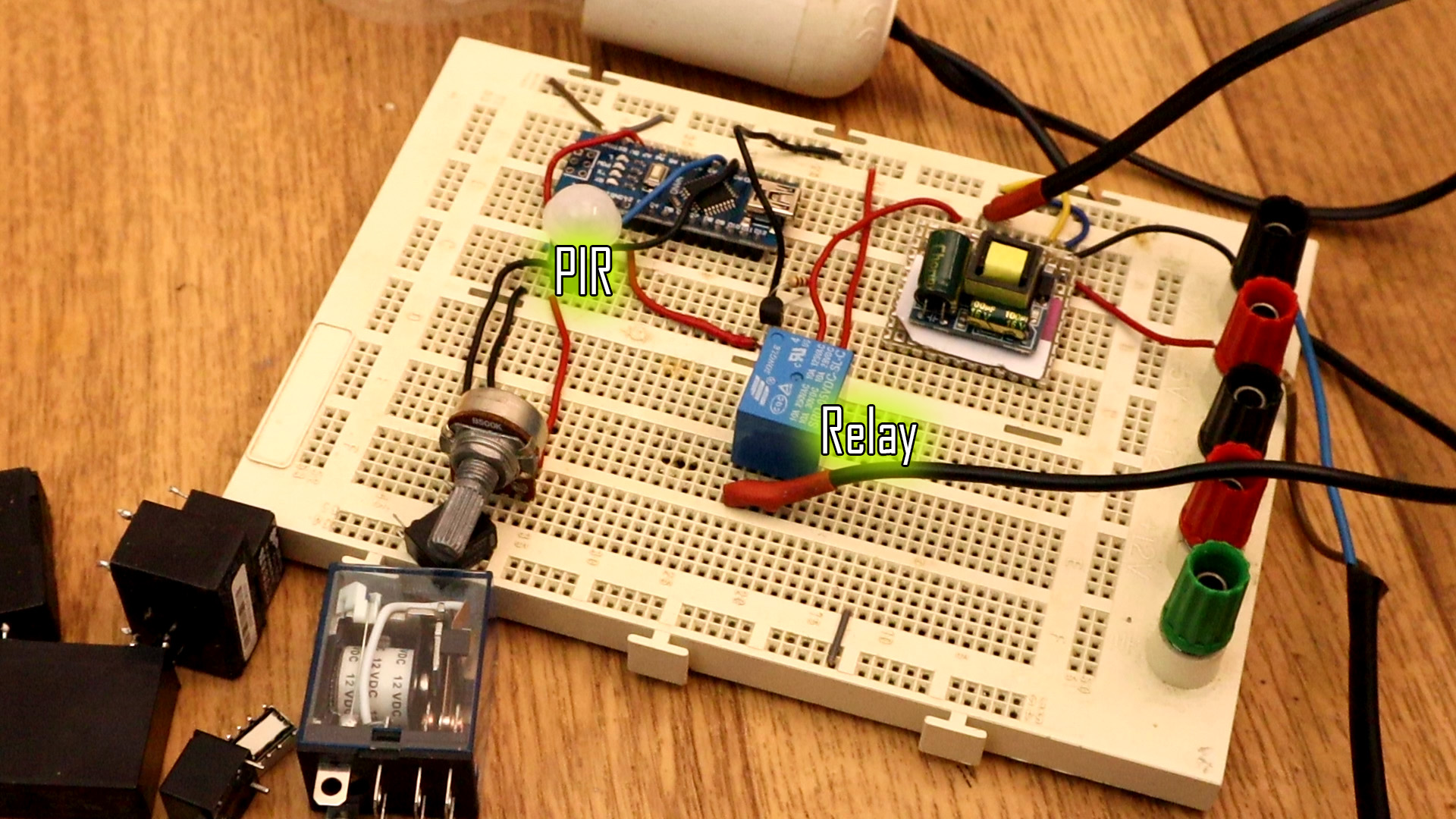
Below we can see the regulator that supplies 12V to the relay and the Arduino Vin pin. The PIR module is connected to the Arduino and the Arduino to a NPN transistor that activates the relay. The Relay is NO (noramlly open) so when we activate the transistor it will be closed so the light bulb is turned on.