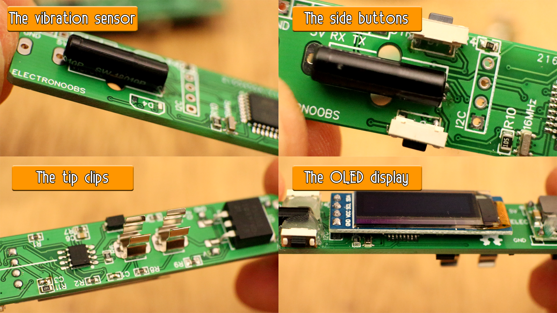
Now we can solder the remaining components such as the vibration sensor and the side push buttons. The board I've made didn't had the wings pads for the buttons, that's why I've put some hot hlue behind the buttons. But the final GERBER file has the wing pads for the buttons so solder those as well. Next we solder the clips for the T12 tip.
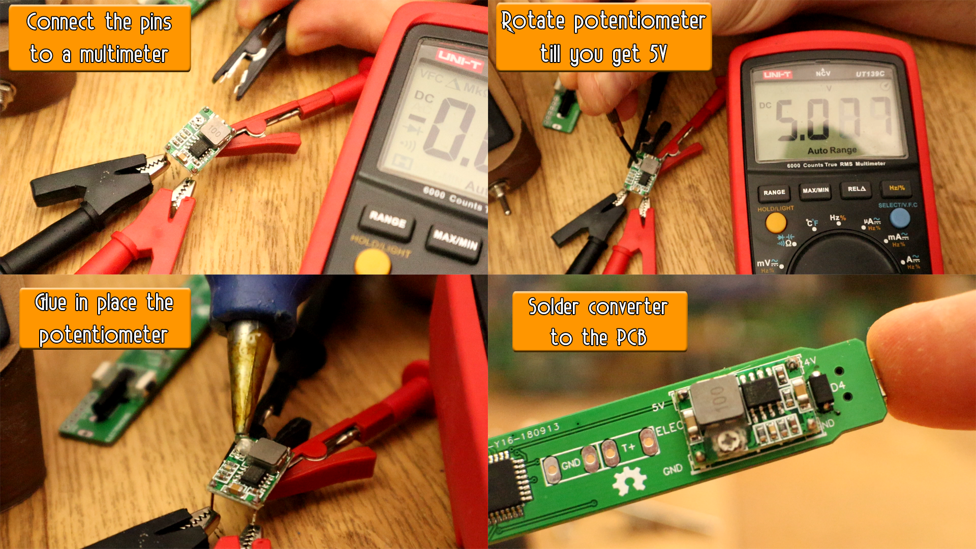
Ok, now, before we add the buck converter, we have to make sure its output is exactly 5V and it will stay that way. Connect it to a multimeter and apply 20V at the input. Rotate the potentiometer till you get exactly 5V. Then glue the potentiometer with some glue so it won't change its value. Now we can solder the buck converter in place. Make sure which is OUT and In as shown on the PCB.
The baord is complete. As a final test, check for shorts on all pads and then connect 20V to the USB input and see if we have 5V at the 5V pins. Is time to program the baord. For that you will have to download and install some libraries for the Arduino IDE and downlaod the last firmware V3.3 for this board.
///////////////////////////////////////////////////////////////////////////////////////////////////////////////////////////////////////
//////////////////////////////////////////YOU COULD CHANGE THIS VALUES IF YOU NEED TO//////////////////////////////////////////////////
///////////////////////////////////////////////////////////////////////////////////////////////////////////////////////////////////////
//Editable Variables (change these values below to fit your project)
String Version = "Version 3.3";
float min_temp = 200;                            //This is the minimum temperature that the iron could get
float max_temp = 500;                            //This is the maximum temperature that the iron could get
float Delay=300;                                 //Refresh rate. This is the time in ms the loop runs (PID+temperature read)
int   setpoint = 280;                            //Temperature setpoint initial value
int   sleeptime = 1;                             //Wait to enter into sleep mode. Time in minutes
int   max_sleeptime = 10;                        //This is the maximum sleep time you could set the iron
int   sleeptime_adress = 2;
int   setpoint_adress_low = 3;
int   setpoint_adress_mid = 4;
int   setpoint_adress_high = 5;
///////////////////////////////////////////////////////////////////////////////////////////////////////////////////////////////////////
///////////////////////////////////////////////////////////////////////////////////////////////////////////////////////////////////////
///////////////////////////////////////////////////////////////////////////////////////////////////////////////////////////////////////

/*PID variables. Fine tune this values. Start with P=1 and D and I = 0. Start increasing till you get good results*/
float Kp=7.58, Ki=0.050, Kd=0.86, Hz=10;          /*My values: Kp=7.98, Ki=0.055, Kd=0.86, Hz=10;*/
int output_bits = 8;                              //With 8 bits, maximum PID output is 255, and that's waht we need for analogWrite
bool output_signed = false;
FastPID myPID(Kp, Ki, Kd, Hz, output_bits, output_signed);
///////////////////////////////////////////////////////////////////////////////////////////////////////////////////////////////////////
The new firmware, the V3.3 has some extr settings. If you press both buttons we get into sleep mode. If you press the bottom button while in sleep mode, you will enter settings. Here you can change the sleep time and the preset temperature which is the temperature that the iron starts with. These values get saved into the EEPROM of the Arduino so each time you restart the iron, those values will be on. See example in the video below. Stay tuned for future updates. I'll make a version where you could change the PID constants using the push buttons as well.
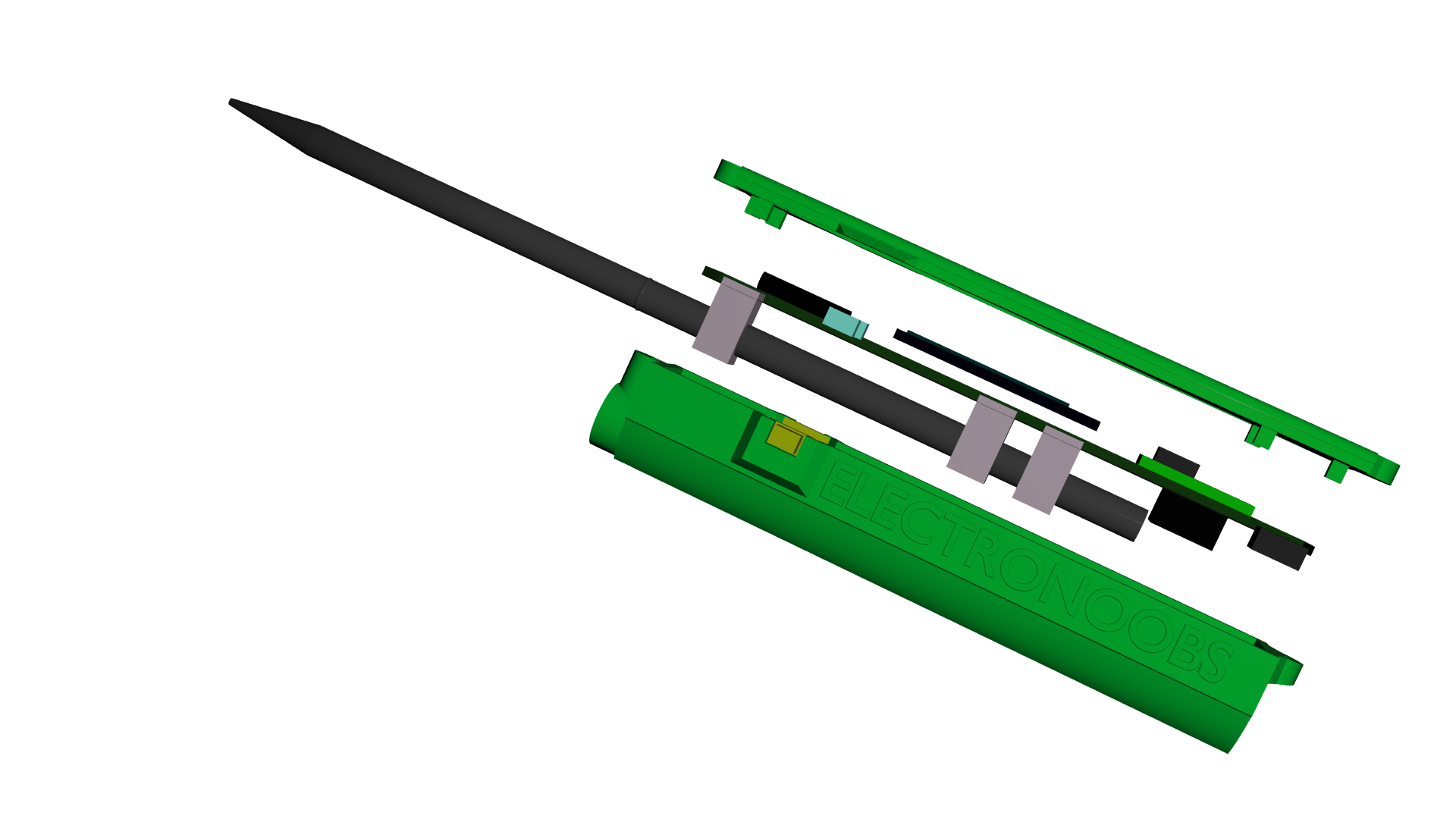
Ok, so below you have the .STL files for the 3D case. Dwonlaod each file and print them. They are already oriented so you don't have to do enything. The case is made out of 4 parts. The top aprt, the bottom part and two small push buttons. I've used PLA material for each. Alos, a 0.4mm nozzle of my printer, 0.2mm layer height, 2 perimeters and 100% infill at a temperature of 200ºC.
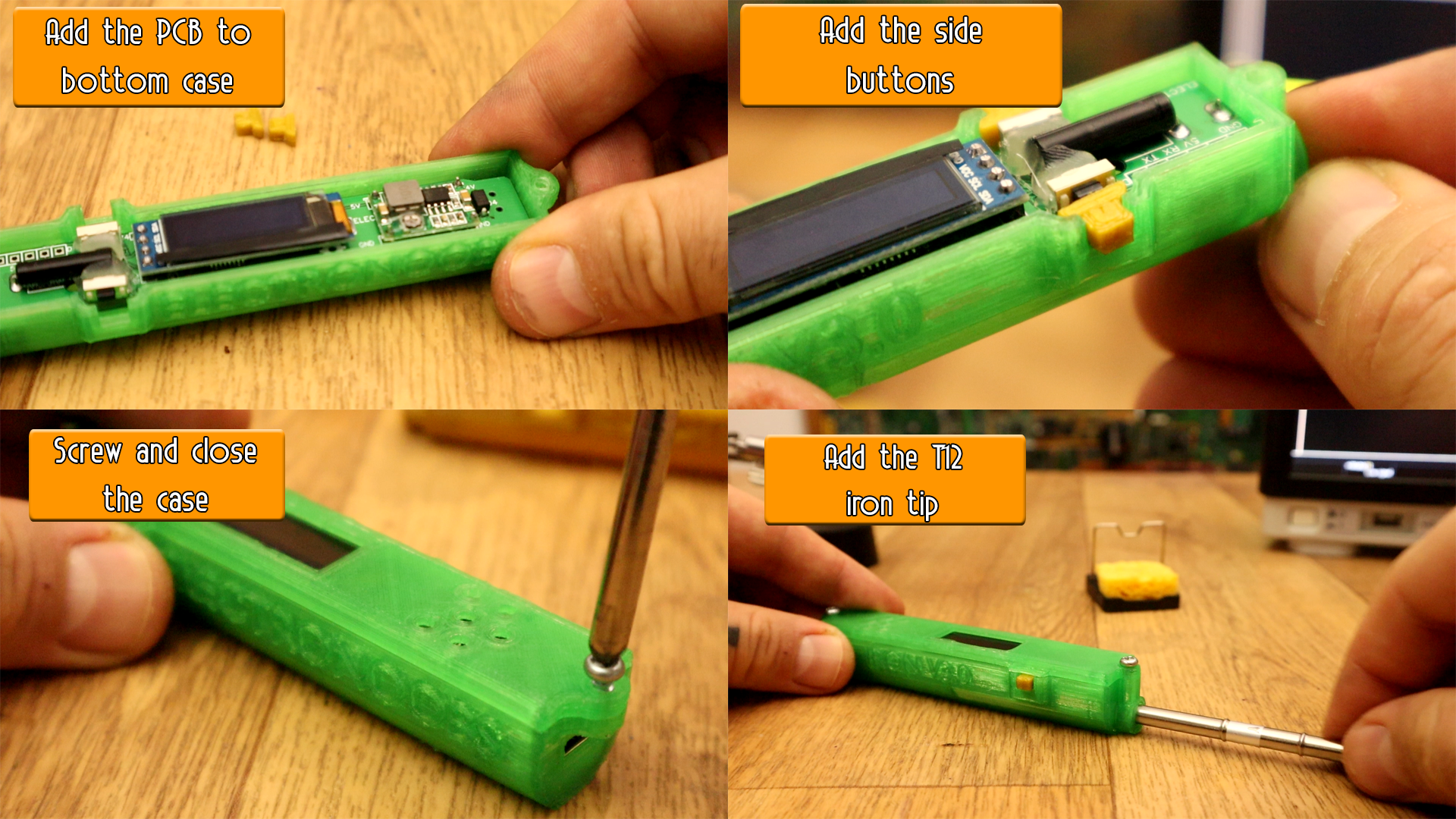
To mount the final product just put the PCB on the bottom part of the case without the T12 tip. Make sure it fits ok in place. If there is not enough space, just slightly use the other soldering iron or a hot nail to melt a bit the plastic supports inside the case. Then add the buttons on each side. use some sandpaper for the buttons so they can moove freely. Then add the top part of the case and close it with two screws. Add the T12 tip and the product is ready.