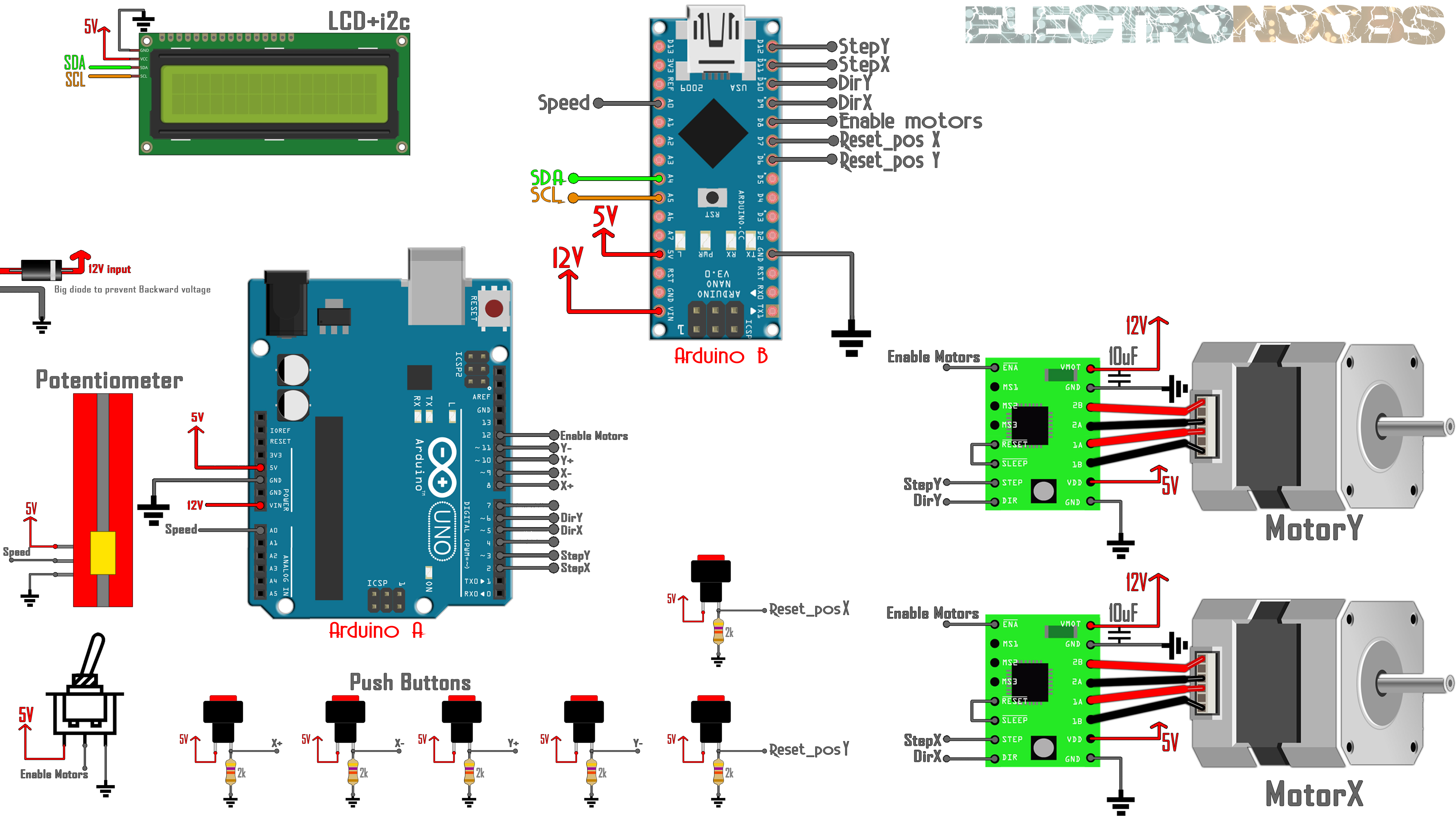
This is code for Arduino A. Download the .zip file below. Open the Arduino (.ino) code on your Arduino IDE and upload it to the Arduino NANO (Arduino A, see schematic). Make sure you have connections in the schematic below. You could download the code from the link below or also copy and paste the code from below.
/*
Code by: ELECTRONOOBS, 07/11/2018
Tutorial webpage: https://www.electronoobs.com/eng_arduino_tut48.php
Schematic: https://www.electronoobs.com/eng_arduino_tut48_sch1.php
Youtube channel: https://www.youtube.com/c/ELECTRONOOBS
*/


//Code for Arduino B (the Arduino with the LCD screen 20x4)
#include  //Downlaod this library here: https://www.electronoobs.com/eng_arduino_liq_crystal.php
#include
LiquidCrystal_I2C lcd(0x27,20,4);  //sometimes the adress is not 0x3f. Change to 0x27 if it dosn't work!!

//Inputs or outputs
int reset_posx = 7;
int reset_posy = 6;
int en_mot = 8;
int dir_x = 9;
int dir_y = 10;
int step_x = 11;
int step_y = 12;
int speed_in = A0;


////////////////////////////////////////////////////////////////////////////////////
////////////////////////////////EDITABLE VARIABELS//////////////////////////////////
////////////////////////////////////////////////////////////////////////////////////
float turns_per_cm = 3.5;             //This is the amount of turns your lead screw needs for one turn.
float steps_per_revolution = 200;   //This is the amount of steps the motor needs for one full rotation
float max_speed = 17;               //Speed in mm per second
float min_speed = 0.6;              //Speed in mm per second
int refresh_rate = 100;             //Each 100ms we print the values on the LCD screen
////////////////////////////////////////////////////////////////////////////////////
////////////////////////////////////////////////////////////////////////////////////


//Other variables used in code
float DELAY = 0;
float RealSpeed = 0;
float mm_per_step = 0.007142;     //Initial value inc ase of 7 turns per cm and 200 steps per full rotatio
unsigned long previousMillis = 0;
bool step_x_state = false;
bool step_y_state = false;
int step_count_x = 0;
int step_count_y = 0;
float mm_x = 0;
float mm_y = 0;
float max_delay = 0;
float min_delay = 0;
int press_counter = 0;

void setup() {
  //Start the screen and print the ELECTRONOOBS logo
  lcd.init();
  lcd.backlight();
  lcd.setCursor(0,0);
  lcd.print("    ELECTRONOOBS    ");
  lcd.setCursor(0,1);
  lcd.print("                    ");
  lcd.setCursor(0,2);
  lcd.print("      WELCOME!      ");
  delay(1500);

  //Uncomment this part for the 16x2 LCD type. Also comment the part below for the LCD
  /*
  lcd.setCursor(0,0);
  lcd.print("Speed:          ");
  lcd.setCursor(6,0);
  lcd.print(RealSpeed);
  lcd.setCursor(12,0);
  lcd.print("mm/s");
  lcd.setCursor(0,1);
  lcd.print("X:              ");
  lcd.setCursor(2,1);
  lcd.print(mm_x,2);
  lcd.setCursor(8,1);
  lcd.print("Y:              ");
  lcd.setCursor(10,1);
  lcd.print(mm_y,2);
  */
  //Print title, x, y and speed on the LCD screen
  lcd.setCursor(0,0);
  lcd.print(" MANUAL CNC CONTROL ");

  lcd.setCursor(0,1);
  lcd.print("X:              ");
  lcd.setCursor(2,1);
  lcd.print(mm_x,2);
  lcd.setCursor(18,1);
  lcd.print("mm");

  lcd.setCursor(0,2);
  lcd.print("Y:              ");
  lcd.setCursor(2,2);
  lcd.print(mm_y,2);
  lcd.setCursor(18,2);
  lcd.print("mm");

  lcd.setCursor(0,3);
  lcd.print("Speed:          ");
  lcd.setCursor(6,3);
  lcd.print(RealSpeed);
  lcd.setCursor(16,3);
  lcd.print("mm/s");

  //Define the pins as inputs
  pinMode(reset_posx,INPUT);
  pinMode(reset_posy,INPUT);
  pinMode(en_mot,INPUT);
  pinMode(speed_in,INPUT);
  pinMode(step_x,INPUT);
  pinMode(step_y,INPUT);
  pinMode(dir_x,INPUT);
  pinMode(dir_y,INPUT);

  //Enable interruptions on pins D8 to D12 for the Step and Direction read
  PCICR |= (1 << PCIE0);    //enable PCMSK0 scan
  PCMSK0 |= (1 << PCINT0);  //Set pin D8 trigger an interrupt on state change.
  PCMSK0 |= (1 << PCINT1);  //Set pin D9 trigger an interrupt on state change.
  PCMSK0 |= (1 << PCINT2);  //Set pin D10 trigger an interrupt on state change.
  PCMSK0 |= (1 << PCINT3);  //Set pin D11 trigger an interrupt on state change.
  PCMSK0 |= (1 << PCINT4);  //Set pin D12 trigger an interrupt on state change.

  //Calculate the delay in order to control speed.
  mm_per_step = (10/turns_per_cm)/steps_per_revolution;
  max_delay = min_speed*20000;
  min_delay = max_speed*23;
}

void loop() {
  //Read the analog input on A0 and map the delay between min an max delay for the speed
  int analog_in = analogRead(speed_in);
  DELAY = map(analog_in,0,1024,max_delay, min_delay);
  RealSpeed = (1000000/DELAY)*mm_per_step;

  //Reset X distance alone
  if(digitalRead(reset_posx) && !digitalRead(reset_posy))
  {
    if(press_counter > 3)
    {
      step_count_x = 0;
      //step_count_y = 0;
      press_counter = 0;
    }
    press_counter = press_counter + 1;
  }

  //Reset Y distance alone
  if(!digitalRead(reset_posx) && digitalRead(reset_posy))
  {
    if(press_counter > 3)
    {
      //step_count_x = 0;
      step_count_y = 0;
      press_counter = 0;
    }
    press_counter = press_counter + 1;
  }

  //Reset both X and Y distance
  if(digitalRead(reset_posx) && digitalRead(reset_posy))
  {
    if(press_counter > 3)
    {
      step_count_x = 0;
      step_count_y = 0;
      press_counter = 0;
    }
    press_counter = press_counter + 1;
  }

  //Calculate the distance by multiplying the steps by the distance made by each step
  mm_x = step_count_x * mm_per_step;
  mm_y = step_count_y * mm_per_step;
  unsigned long currentMillis = millis();  //Save current time
  //here each "refresh rate" we print the values on the LCD screen
  //We print spee, distance X and Y
  if(currentMillis - previousMillis >= refresh_rate){
    previousMillis += refresh_rate;
    /*PREVIOUS setup for 2 row LCD
    lcd.setCursor(6,0);
    lcd.print("      ");
    lcd.setCursor(7,0);
    lcd.print(RealSpeed,2);    //Print speed
    lcd.setCursor(2,1);
    lcd.print("      ");
    lcd.setCursor(2,1);
    lcd.print(mm_x,2);        //Print distance made for X axis
    lcd.setCursor(10,1);
    lcd.print("      ");         //Print distance made for y axis
    lcd.setCursor(10,1);
    lcd.print(mm_y,2);         //Print distance made for y axis
    */

    //Print the distance and speed
    lcd.setCursor(0,1);
    lcd.print("X:                ");
    lcd.setCursor(2,1);
    lcd.print(mm_x,2);
    lcd.setCursor(18,1);
    lcd.print("mm");

    lcd.setCursor(0,2);
    lcd.print("Y:                ");
    lcd.setCursor(2,2);
    lcd.print(mm_y,2);
    lcd.setCursor(18,2);
    lcd.print("mm");

    lcd.setCursor(0,3);
    lcd.print("Speed:            ");
    lcd.setCursor(6,3);
    lcd.print(RealSpeed);
    lcd.setCursor(16,3);
    lcd.print("mm/s");
  }
}//End void loop


//interruption to detect steps for X and Y
ISR(PCINT0_vect){


  if (!(PINB & B00000001)){                           //If enable is activated (EN is negative enabeled)

    if(PINB & B00000010 ){                            //If D9 is HIGH, motor turns right so we increase steps
      if(PINB & B00001000 ){                          //If D11 is high we have one step detected
        if(step_x_state == 0){
          step_x_state = 1;
          step_count_x = step_count_x + 1;            //Increase steps by 1
        }
      }

      else if(step_x_state == 1){                     //If D11 is LOW we have another step detected
        step_x_state = 0;
        step_count_x = step_count_x + 1;              //Increase steps by 1
        }
    }//X_up D9

    if (!(PINB & B00000010 )){                         //If D9 is LOW, motor turns left so we decrease steps
      if(PINB & B00001000 ){
        if(step_x_state == 0){
          step_x_state = 1;
          step_count_x = step_count_x - 1;             //Decrease steps by 1
        }
      }

      else if(step_x_state == 1){
        step_x_state = 0;
        step_count_x = step_count_x - 1;                //Decrease steps by 1
        }
    }//X_down D9


    //Now we do the same but for Y
    ////////////////////////Y////////////////////////

    if(PINB & B00000100 ){
      if(PINB & B00010000 ){
        if(step_y_state == 0){
          step_y_state = 1;
          step_count_y = step_count_y + 1;
        }
      }

      else if(step_y_state == 1){
        step_y_state = 0;
        step_count_y = step_count_y + 1;
        }
    }//X_up D9

    if (!(PINB & B00000100 )){
      if(PINB & B00010000 ){
        if(step_y_state == 0){
          step_y_state = 1;
          step_count_y = step_count_y - 1;
        }
      }

      else if(step_y_state == 1){
        step_y_state = 0;
        step_count_y = step_count_y - 1;
        }
    }//X_down D9


  }//End EN enabled

}//End ISR