We've been working on this setup for a while. We wnated to control two axis of a CNC machine manually. You could add this setup to any CNC machine. In my case was to a milling machine and in case of Alpha Mods was in case of a precision table for tower drill. The setup has an LCD so we could see the distance. Then we have push buttons to move the axis and also to reset the position to 0. A sliding potentiometer will set the speed in mm/s.
First of all, let's analyze the schematic.
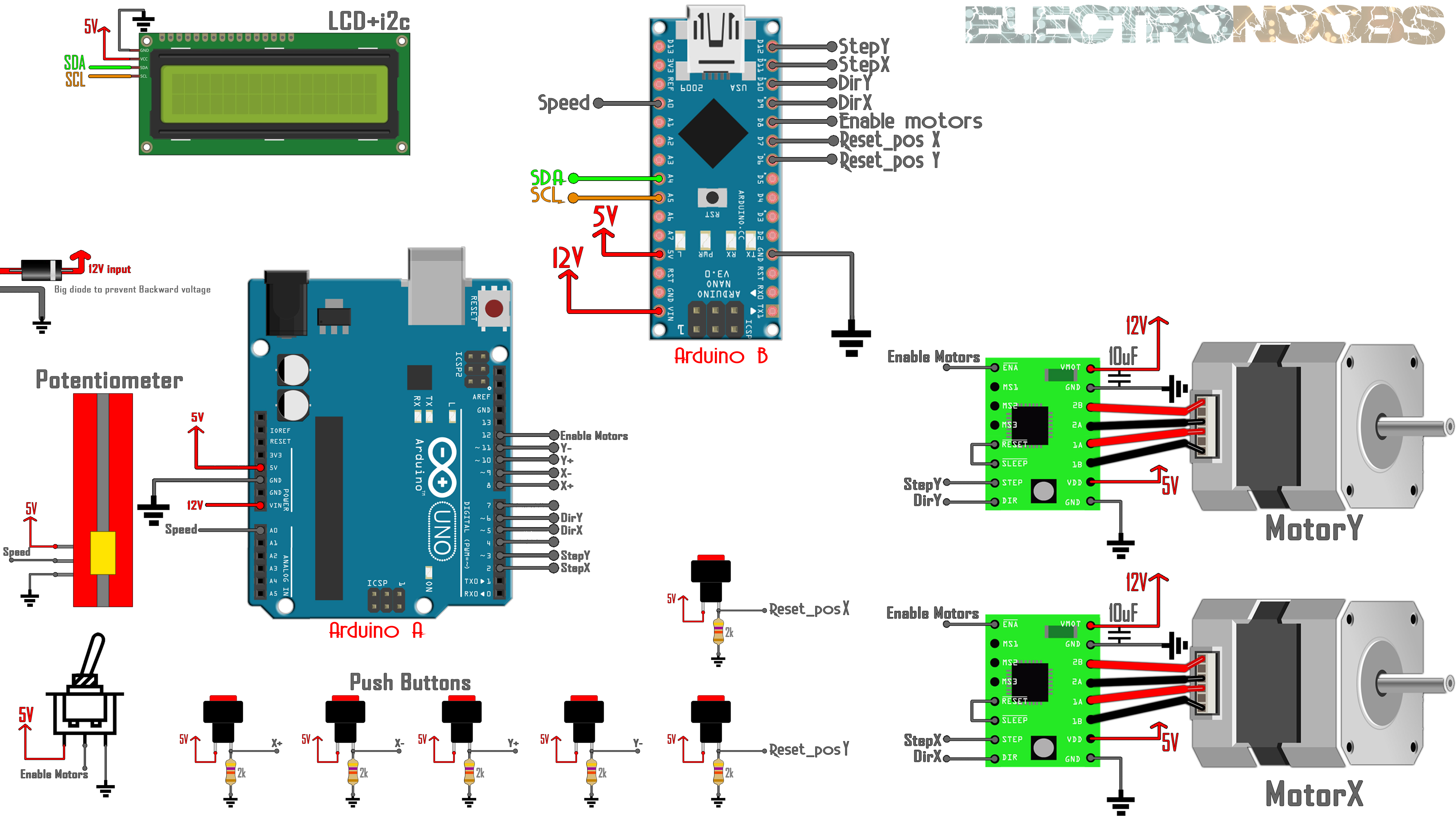
We have 2 step motors. I've used NEMA 17. Each with a A4988 driver. This driver needs 3 signals from the Arduino. Enable, direction and steps. The Enable pin is connected to a toggle switch so we could start ot stop the motors manually. The toggle switch is also connected to the Arduinos so we could know when the motors are enabeled or not. To control speed we use a lineal potentiometer and to move axis and reset position, some push buttons with pulldowns. To print the distance, I've used a i2c LCD screen of 20x4 but you will have the code for the 16x2 version of LCD as well.
Since there is not enough space, I had to use more than one pin for the GND rail. I've used 3 wires that I've soldered together as you can see in the picture below. So now we have 8 pins, 7 for the segments and 1 for GND. The base of out tube is ready. Test each LED connection before closing the tube. All is there to do is to place a plastic bottle over. If you ahve glass bottle even better!!!
////////////////////////////////////////////////////////////////////////////////////
////////////////////////////////EDITABLE VARIABELS//////////////////////////////////
////////////////////////////////////////////////////////////////////////////////////
float turns_per_cm = 3.5;             //This is the amount of turns your lead screw needs for oen turn.
float steps_per_revolution = 200;   //This is the amount of steps the motor needs for one full rotation
float max_speed = 17;               //Speed in mm per second
float min_speed = 0.6;              //Speed in mm per second
////////////////////////////////////////////////////////////////////////////////////
////////////////////////////////////////////////////////////////////////////////////
Make the connections as in the Schematic above. Then uplaod code B and A to the Arduinos. Supply 12V to the main input and then press the buttons. The motors will rotate and the axis will ove at the defined speed. If you want to rotate the motors with your hand, you can't. For that, you have to disable the motor drivers. For that we use the toggle switch. If that is disabeled, we can rotate the motors without power and taht could be usefull as well.
To control the direction, we set the "dir" pin to high or low for left or right. To make steps, we have to send a pulse signal to the "Step" pin. The frequency of this fulse signal will give the speed of rotation since each level change of the signal represents a step made by the motor. In the video below, you can see that the bigger is the width of the pulse (lower frequency), the motor will rotate slower.
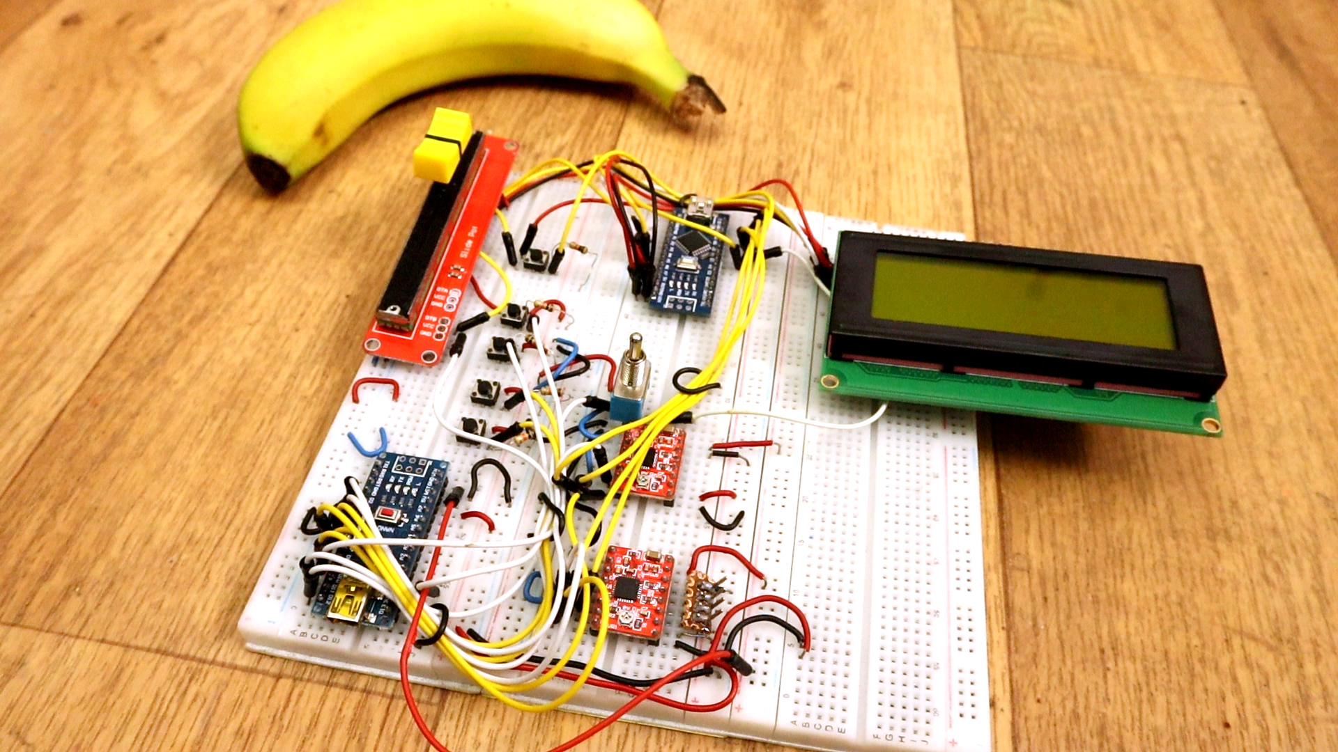
Ok, as you have seen, in my case I've mounted the circuit on a breadboard. If you want a more professional look, download the board from below. Downlaod the GERBERs and send them to JLCPCB or any other PCB service. Below you will also find the easyEDA project and the schematic.