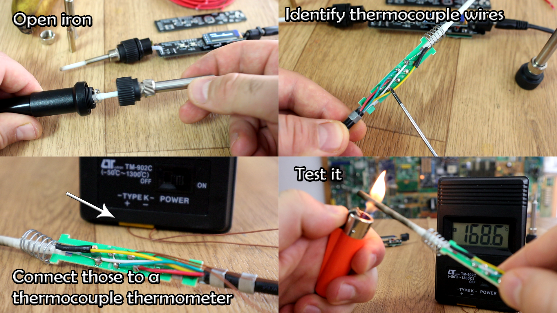
Open the commercial soldering iron. As we can see below, it has 5 wires. 2 for the heater, 2 for thermocouple and 1 is earth. The heater doesn't matter, it has no polarity. But the thermocouple has polarity so we have to find that. Solder wires to the thermocouple and connect those to a k-type thermometer. If you get a good read, well, now you now the polarity.
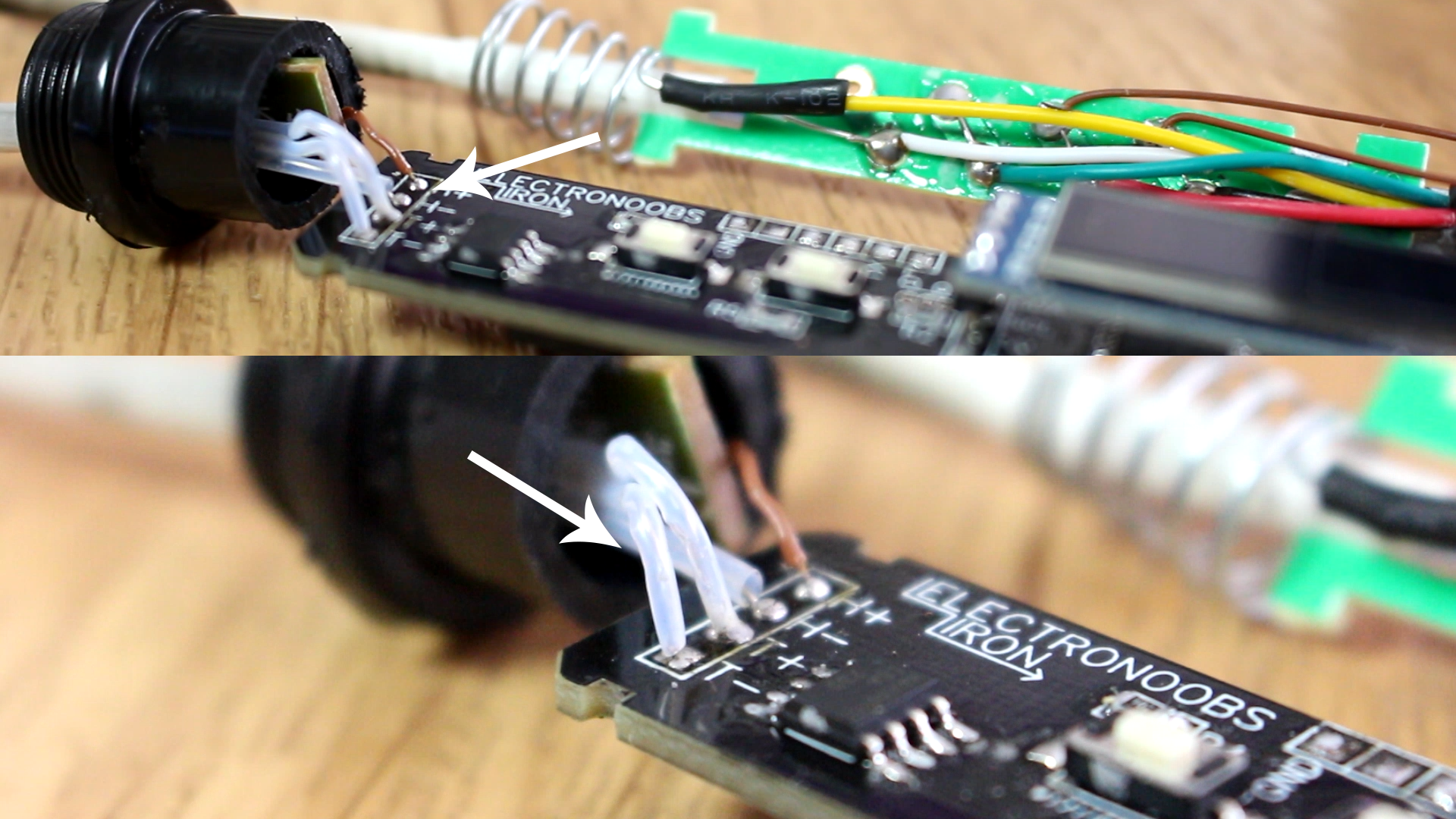
Now, solder the heater and thermocouple to the PCB and we can jump to the code part. The heater is marked with H+ and H- and the thermocouple with T- and T+ on the PCB. Don't worry about the heater polarity, but be careful witht the thermocouple.
Below you have the code that has to be uploaded. Connec the FTDI module to the UART ports and uplaod the next code. Make sure, you ahev the MAX6675 and OLEd libraries installed as we haev seen before. The code is easy. Read all the comments in the code to understand more and also look at my PID temperature controller video. The idea goes like this. We start in sleep mode. We press any of the buttons and get out the sleep mode and then create a PID code. In another loop we read the temperature using SPI communication, calculate the error and finally get the PID value. Next, we write a PWM signal to the MOSFET connected on pin D3. And that’s it. There are other small "ifs" in the code that will increase or decrease the set temperature value or start the sleep mode.
//Start PID code
  unsigned long currentMillis = millis();
  if(  (currentMillis - previousMillis >= Delay) &&  (!sleepmode && !temp_change)){
    previousMillis += Delay;
    if(!sleepmode)
    {
      temperature_read = (ktc.readCelsius());
      error = set_value - temperature_read + 3;
      error_percent = (error/set_value)*100.0;

      P_pid = kp * error;
      I_pid = I_pid + (ki * error);
      D_pid =  kd*((error - previous_error)/(Delay/1000)); //The delay is 1000 defined at the begginning
      PID_value = P_pid + I_pid + D_pid;
 	  if(PID_value > 255)
      {PID_value = 255;}
      if(PID_value < 1)
      {PID_value = 1;}
      //Write PWM signal to MOSFET on D3
      analogWrite(mosfet,PID_value);
Once uplaoded, test if it works. Connect 12 to 24V to the DC plug. It will start with the logo, then in sleep mode. press any button and change the temperature. It can reach up to 480 degrees. If it works, is time to add the plastic case.
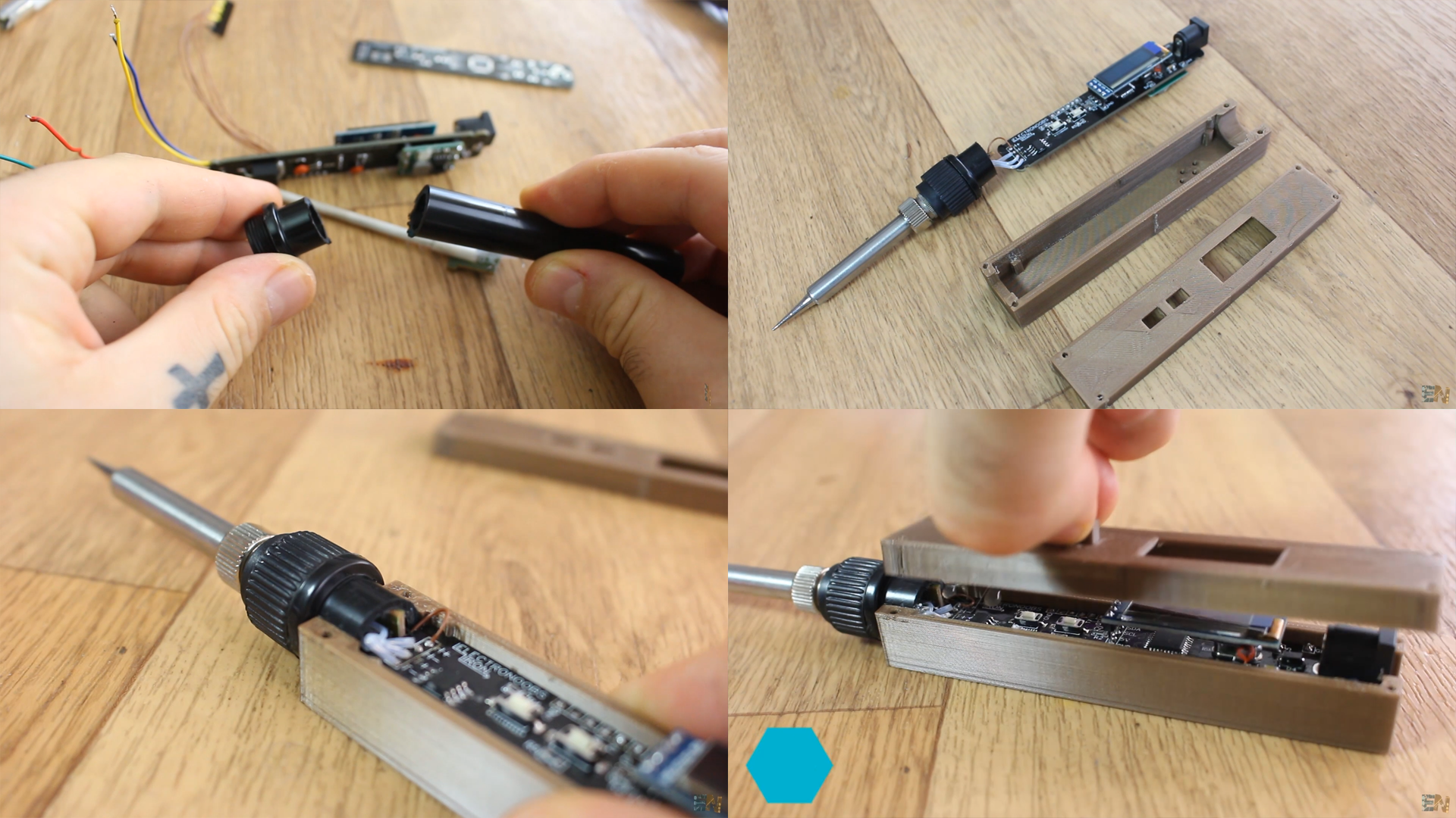
For the case, I first shorten the stock wires and soldered the heater to my PCB. Next, I first cut the plastic case of the other iron that I’ve bought. I then designed and 3D printed a case for the electronics. The case is made out of two parts and 2 buttons. I use this plastic part from the commercial iron because is more heat resistant and already has the part where I can screw the tip.
I pass the wires through this plastic part and solder them on to my PCB. I remove the UART cables since the Iron is already programmed and test it once again with voltages from 12 to 24 volts.
I get the 3D printed case. I fit the PCB inside, the size is peret. When I’m sure everything is ok, I use a bit of hot glue. I add the small plastic buttons and close the top part. And there you have it.
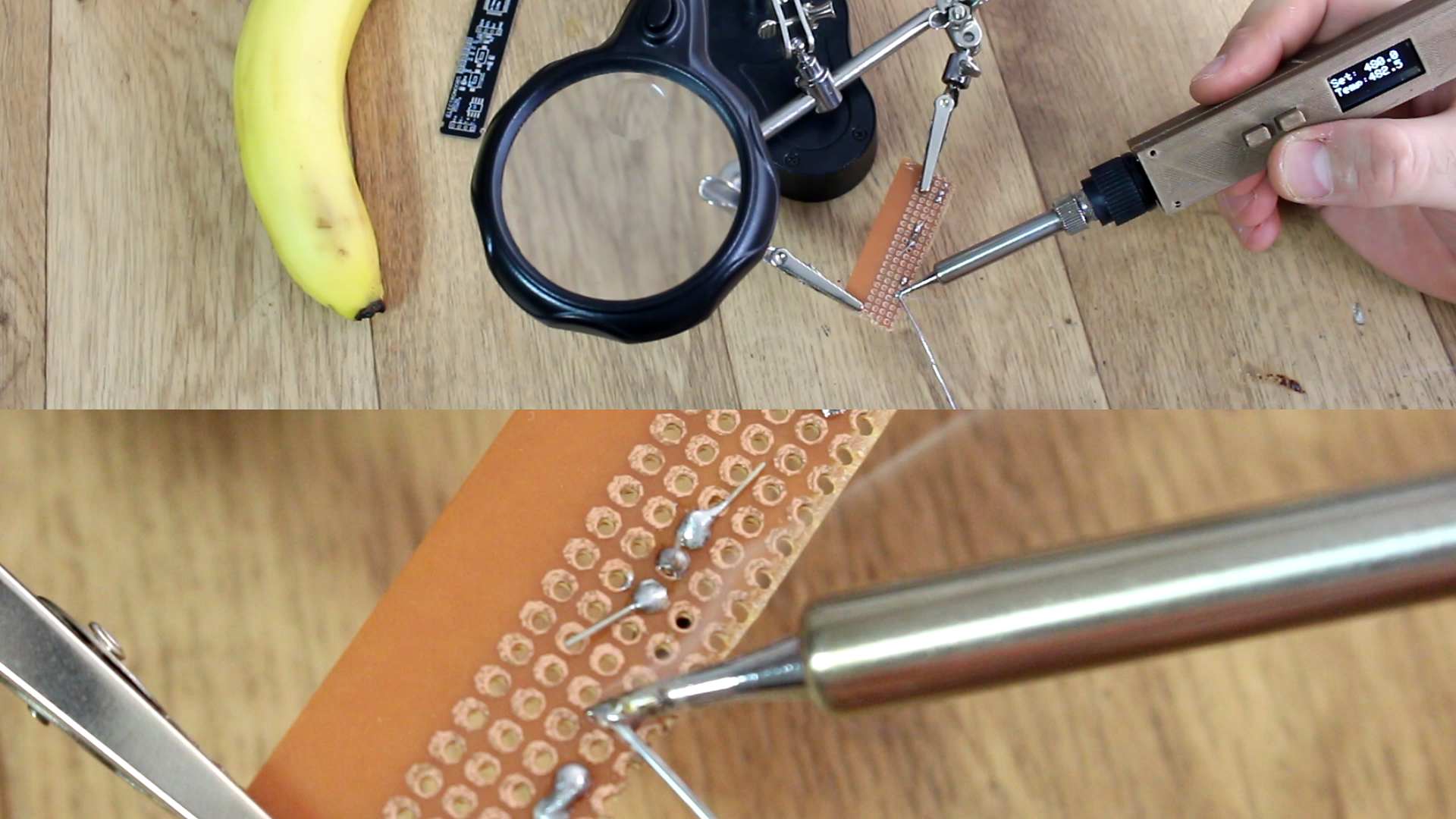
Glue the case and the project is done. Now, connect the power and use the buttons and test if it can solder well. Let’s talk a bit about it and future improvements. First of all, with a battery of 14V I couldn’t reach the maximum temperature. But with 24V It had no problems. Other disadvantage is the bad quality of the iron metal tips because it is very cheap. The heater gets quite hot but the heat is not well transferred and you end up with a bad iron.
I think I’ll make more research and test with the TS100 tip because it is a very high quality one and work’s very well. Also, next version will have a hall sensor and a magnet on the stand so I could implement auto sleep mode in the firmware. There you have it my friends. You have all the files in this tutorial.
If you consider helping my projects, here is my PATREON page, THANK YOU!