


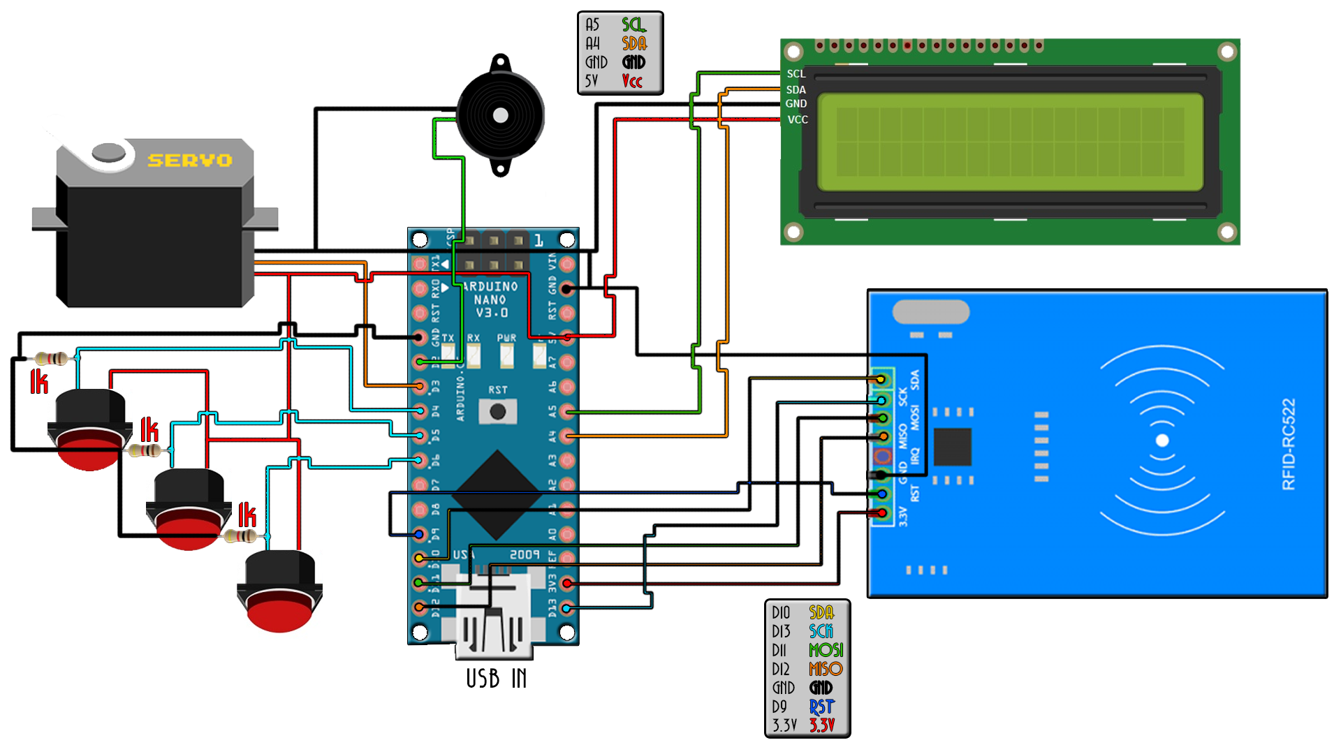
This below is the schematic of the final project. I’ve added an LCD in order to send notifications to the user and 3 push buttons. The LCD uses i2C communication so make sure you install the i2c LCD library that you could also find in the description below. One push button is for outside closing the door and the other two are for inside close and open the door. If you are outside the room you could close the door with the button but open it only with the RFID tag. If you are inside you could both open or close the door whenever you want using the buttons. Finally, I’ve also added a buzzer for sound notifications, this will make the project less boring and add little sound.
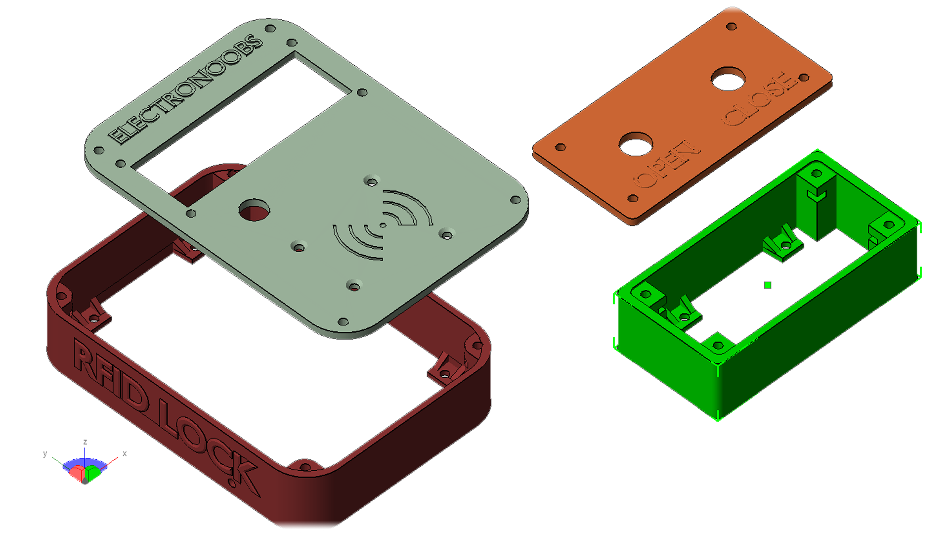
I’ve designed a small case and 3D printed using PLA material and my ANYCUBIC i3 printer. The link for the 3D case is below if you want to build the same project. It has holes for you to screw it on any surface, place for the LCD screen, the RF module and a push button. Also, this another small case for the other two buttons on the other side.
I screw the LCD in place using M3 screws and nuts. I solder everything and also fit the RF sensor on the front side of the case. I supply 12V to the circuit using a DC transformer. The servo motor is connected to pin D3, the RFID module to SPI port and the LCD to A4 and A5, the i2c port.
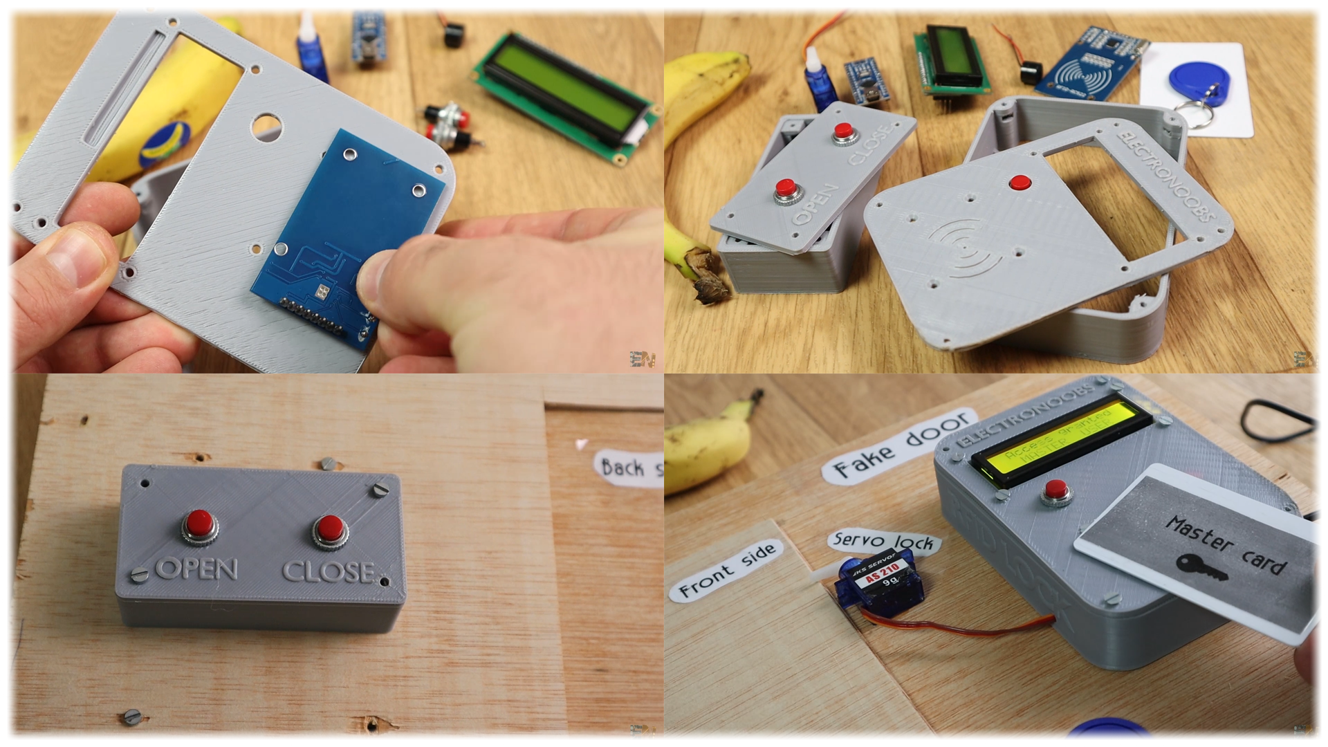
This system could store up to 5 users in my case but if you want more, you would have to copy paste some parts of the code and add more users. I have the RF module and one push button on the outside and the other case on the other side. The servo motor on the inside part of the door connected to an opening system.
Let's see how the code works. First inlcude all the libraries that we need and define the LCD and the MFRC module pins and alsodefine the Servo variable for the motor.
#include <SPI.h>
#include <MFRC522.h>
#include <Servo.h>
//LCD config
#include <Wire.h>
#include <LiquidCrystal_I2C.h>
LiquidCrystal_I2C lcd(0x3f,20,4);  //sometimes the adress is not 0x3f. Change to 0x27 if it dosn't work.
#define RST_PIN  9    //Pin 9 is for the RC522 reset
#define SS_PIN  10   //Pin 10 is the SS (SDA) of RC522 module
MFRC522 mfrc522(SS_PIN, RST_PIN); //Create anew RC522 object
Servo motor_1;
In the setup loop we start the LCD and RFID module and print something on the LCD screen. We attach the motor at pin D3 and set the buzzer pin as an output. Funally using "motor_1.writeMicroseconds(1000);" we put the servo in the closed position.
void setup() {
  SPI.begin();                 //Start a new SPI bus
  mfrc522.PCD_Init();          // Startt the MFRC522
  motor_1.attach(3);           //Set digital pin D3 to be the PWM signal for the servo motor
  pinMode(buzzer_pin,OUTPUT);  //Set digital pin D7 to be the buzzer OUTPUT
  //Config of the i2c LCD screen
  lcd.init();
  lcd.backlight();
  lcd.setCursor(0,0);
  lcd.print("Place card here!");
  lcd.setCursor(0,1);
  lcd.print("                ");
  motor_1.writeMicroseconds(1000);
}
In the void loop, using the functions below we read the ID. Then we check if each of the 4 bytes are the same as the ones that we have stored on the program. If yes, we open the door. If not, we give error.
if ( mfrc522.PICC_IsNewCardPresent())
          {
        //Select the found card
              if ( mfrc522.PICC_ReadCardSerial())
              {
                    // We store the read ID into 4 bytes with a for loop
                    for (byte i = 0; i < mfrc522.uid.size; i++) {
                      ActualUID[i]=mfrc522.uid.uidByte[i];
                    }
}
Very important, make sure you add the push buttons and pullup resistors just as in the schematic, otherwise those pins will be in free air and the signal will wamble around and open and close the door like a crazy system.
So, there you go my friends. Now you know the basics of how RFID system works, how we use RF signal and send data, how the non-powered ID tag responds and how to use this module and make a system for door opening. You have the part list, schematics, 3D files and codes on this post so make sure you check those out. If you would like to support my projects, check my Patreon page, I would really appreciate that guys and by the way, thank you very much to all my Patreons.


