This below is an RFID module that I’ve bought from eBay for very cheap. If you want one as well, check the link below. I get the RF TAG close enough to the RFID module, it detects it, reads the unique ID that the card has and then you could do any process that you want, in our case later, unlock a door.

If we look close enough we can see that the mdoule has the circuit on one side and on the other we can se a PCB coil antenna. We can easily see 4 windings and also a bunch of capacitors. Now if we look at the RFID card, at first sight it seams just like a random plastic card. But if I place it against light we can see once again a coil antenna but also a tiny microchip. So, these two antennas give us some sort if idea of how this communication will work. Let me explain with a bit of more details.
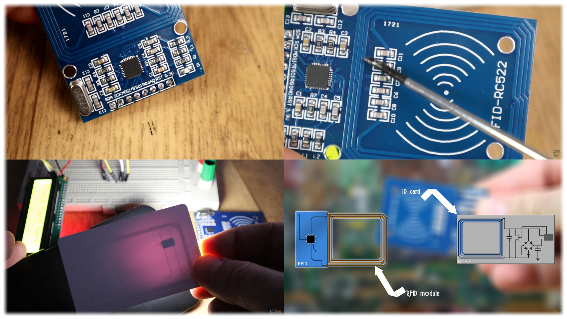
This below will be our radio module and the ID card. They both have some coil antennas, which you all know, that by passing current through a copper wire, they will create a magnetic field wave. But also, a magnetic flux passing through a coil will induce current in that copper winging and that will result in a voltage drop. That’s how the data is sent through air. A magnetic wave is created in the first antenna, and that magnetic field will reach the ID tag antenna.
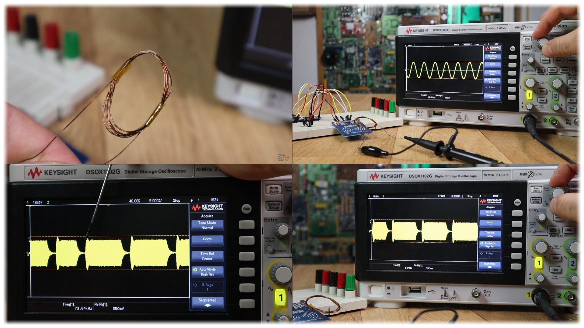
The signal that the RF module sends is RF modulated and works at 13.6kHz as you can see below. The module has a 27.12MHz crystal oscillator but the RF signal is sent at 13.6KHz.
Ok, so we know now how basic RF antennas work, but how these specific modules work? Well, an oscillating radio frequency signal is created in the transmitter antenna as you can see below. The receiver, the ID tag antenna in this case will receive the RF signal. But this plastic tag has no battery or any kind of power. The card will have to send back the unique ID data, so how dose that?
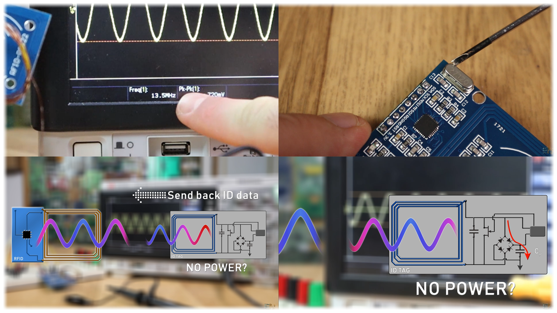
Well, the RF signal that arrives at the receiver will first charge up a capacitor through a rectifying bridge so we would get DC voltage. We name this capacitor, power capacitor since this will be the one providing power to the IC for a short amount of time. So now the internal IC of the TAG card has power. At the input we have another capacitor but way smaller and without rectifying circuit. This capacitor, since it is much smaller, will only smooth the radio waves so the control unit could understand the values. So, the output of this capacitor will be the data in, the output of this one, the power in and finally, we add switch connected to the data out pin. This data out will modulate the response signal and it will use the power stored into the power capacitor and send another signal to the RFID module. That signal will carry all the data inside of the ID tag and that’s how we read the information on this plastic RFID card.
I’ve made a small copper wire coil and connected it to my oscilloscope and set a small code that will send data and try to connect on any RFID device. At first look we can’t see anything but if we go close enough we can see an oscillating RF signal of 13,6KHz. I can’t see changing frequency so I suppose this is not FM signal so it must be AM or amplitude modulated. If I trigger the signal right in the communication time, we can see the modulated signal, so, if this is amplitude modulation the low signal must be 0 and high must be a digital one or something like that. Or maybe the lenght of the FM signal oscilating represents the sent data. I’m not entirely sure of the type of modulation but with these two characteristics, I could say it is AM.
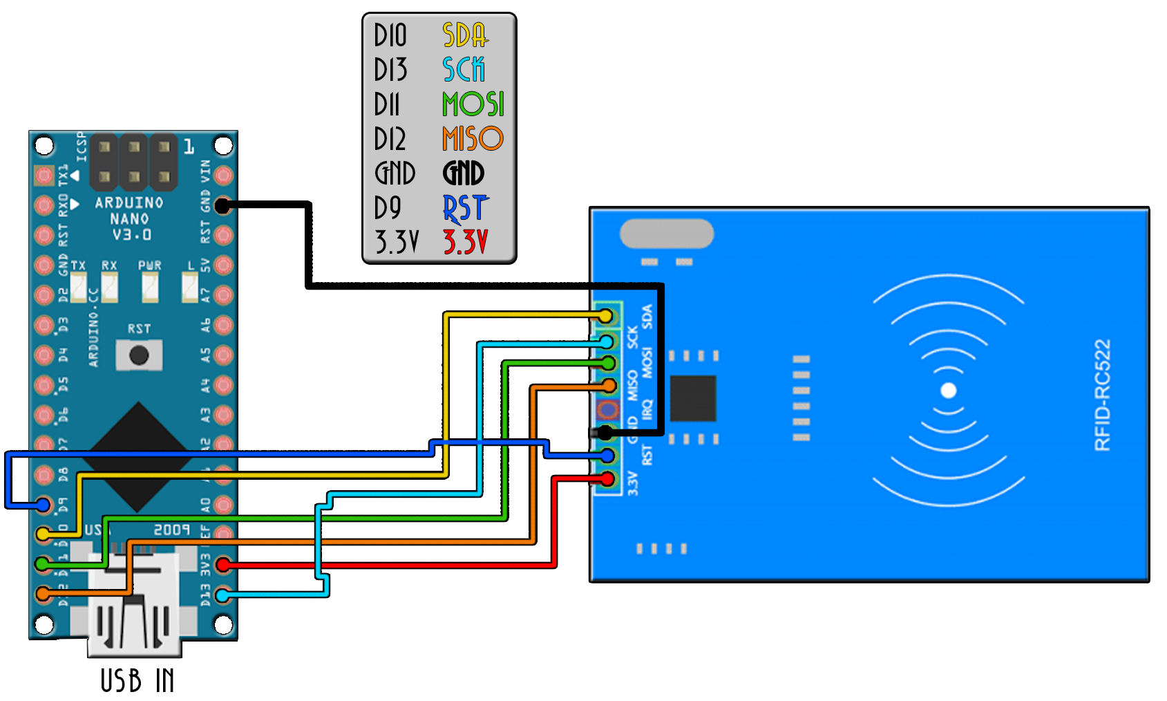
So, now we know how the communication works, let’s connect the RFID module to an Arduino and start working with it. Use the basic schematic below, we connect to the Arduino. Be careful, the module works at 3.3V so supply that voltage to the module. The rest of the pins are 5V compatible so no worries. Connect the SPI pins which are clock, MOSI, MISO and a data pin. Now open Arduino IDE and go to library manager. There search for the MFRC 522 library and install it. If you don’t want to use the manager, just download the library zip file from below and go to sketch, include library, add .zip library and select the downloaded .zip file.
Ok, once installed go to examples, MFRC 522 and open the read ID example. Select the Arduino NANO board, select the com and upload. Now open the serial monitor and set a baud rate of 9600. As you can see below, when I place tag card in front of the sensor, I get the unique ID code in decimal and hexadecimal values. Write these codes down in order to remember the code for each of your tags if you want.

Ok, so now we know the ID of these two tags that come with the module. Using bits from this example code, I’ve made my own code that will detect the scanned card, check the ID and if the ID is on the user list it will open a door with a servo motor. The servo motor is a 9g one and it could be supplied directly with 5V from the Arduino since it won’t draw too much current.