
 About me
  History
  Let's learn
  Contact us
  Arduino tutorials
 Circuits tutorials
  Robotics tutorials
 Q&A
Q&A Blog
Blog  Arduino
  Circuits
 Robotics
  Modules
  Gadgets
  Printers
  Materials
  3D objects
  3D edit
  Donate
  Reviews
  Advertising


Whistling detection Arduino
0. INTRO
Let's build our HOMEMADE whistle detector circuit. The idea is more than simple. Using a microphone we detect sound. Next we amplify that signal two times in order to have a square pulse signal with the same frequency as the input signal from the microphone. Then we connect that square wave to one Arduino input and measure the frequency using interruptions. Next we check if the range is between (800 and 1800Hz in my case) and activate any other loop giving the Arduino something to do. Easy right?
A whistle sound is practically a sine wave.
Usually the frequency of a whistle is between 800 and 2500Hz.
Ok, this is how will the project go. We will build the detecting circuit. We read the frequency with arduino and then we control
Full part list here:
1. Detecting circuit
We will use an electret microphone. Electret Condenser Microphone, as the name suggests is a parallel plate capacitor and works on the principle of a variable capacitance. It consists of two plates, one fixed (called the back plate) and the other moveable (called Diaphragm) with a small gap between them. An electric potential charges the plate. When sound strikes the diaphragm it starts moving, thereby changing the capacitance between the plates which in turn results in a variable electric current to flow.
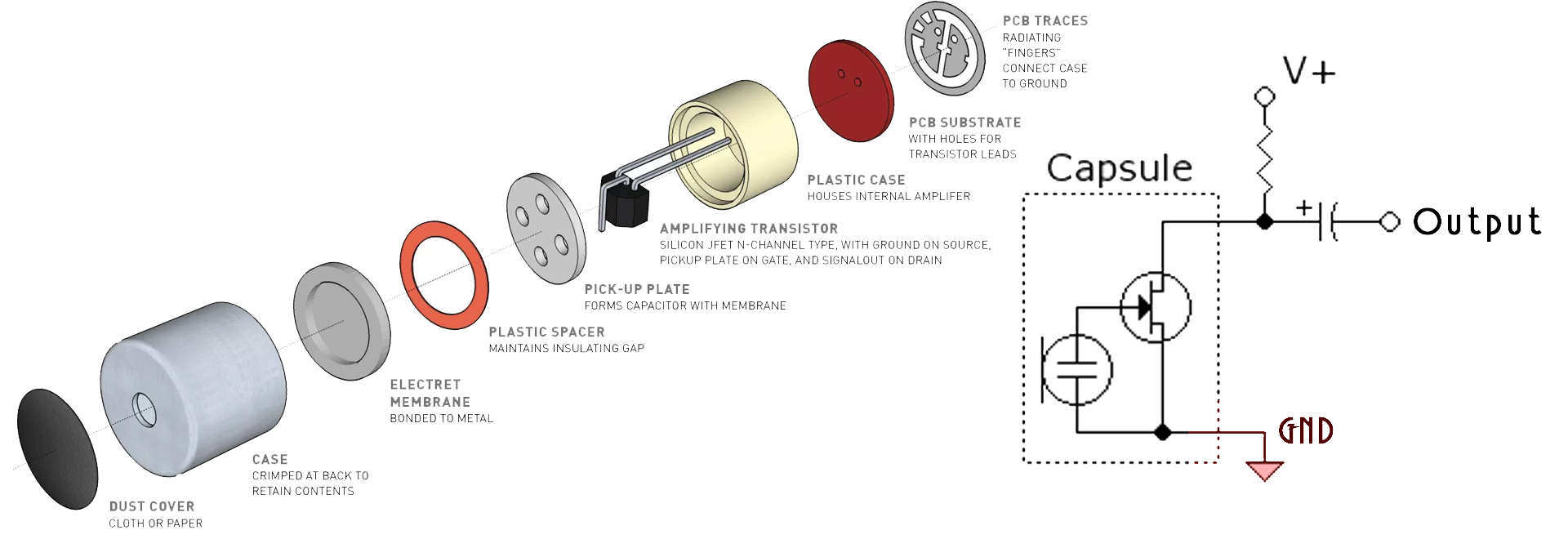
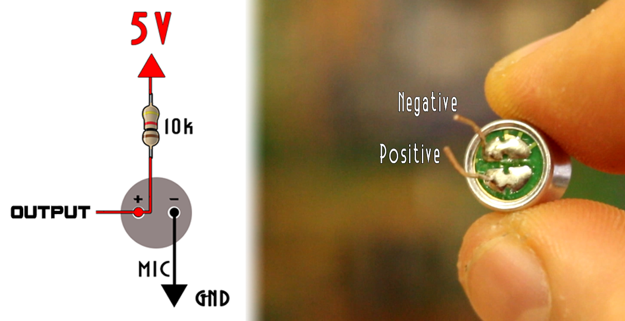
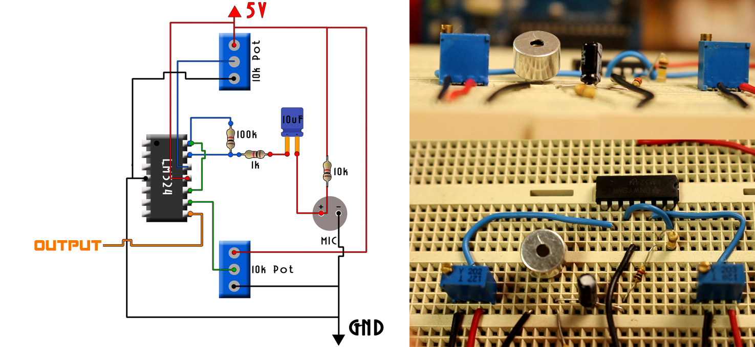
Sound travel through air in a form of a pressure wave. When that wave reaches the inside microphone capacitive plates, that will result in voltage change. The microphone has an internal transistor that will amplify that signal. So, all we have to do is to add a pullup resistor of 10k ohms in this case connected to 5V and the negative pin of the microphone to ground. You can identify the negative pin of the microphone looking at these 3 PCB lines that you could see below.
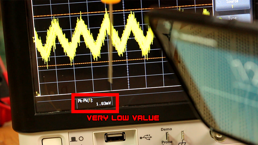
Now the microphone is powered and if we connect the oscilloscope to the output in the scheamtic above, we could observe the audio wave. In the photo below you have an example of a 1200Hz sine sound wave made with an mobile App. As you can see the peak to peak voltage is very, very low.
To amplify the audio signal I’ve used an operational amplifier or better said OPAMP. I've used the LM324 which is not a high-performance amplifier but it will do the job more than perfect for this easy project. Besides it has 4 amplifiers integrated in just one chip, and since we need to amplify two times, this is great.
Ok so now I connect the output from the microphone to a 10uF capacitor as high-pass filter and in series with this capacitor I add 1k ohm resistor. You see, the amplifier gain is given by the two resistors and formula below. I want a gain of 100 so the second resistors should be 100 times bigger than the 1k ohm one.
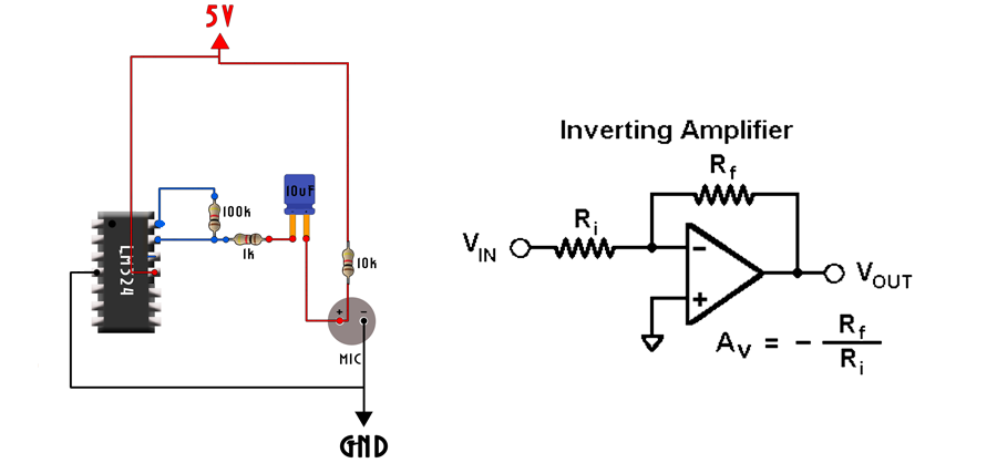
I place the OPAMP on the breadboard and add the 100k ohms resistor between the negative input pin and the output which are pins 13 and 14. Now I supply 5V and ground to the Vcc and GND pins which are pin 4 and 11 of the LM324.
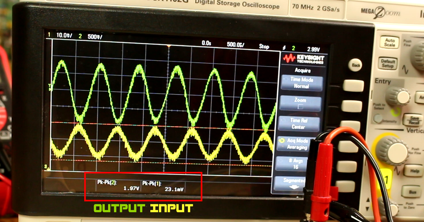
In order to set a certain offset of the output I connect the positive input which is pin 12 to the middle pin of a 10 turns potentiometer. The whistle wave as you can see is a si ne wave wo it will be the same amount of time in the negative side as in the positive side. Since the maximum voltage in this project will be 5V of the Arduino, I want to set the offset exactly in the middle of that voltage. I turn the potentiometer till I get 2.5 volts on the middle pin. By the way, the other two pins of the potentiometer are connected to 5V and GND. Now I observe the output signal on the oscilloscope. I’ve used an Android App to create a sine wave sound. I set the frequency at 1.2KHz and put the smartphone close to the microphone. As you can see below the microphone signal is around 20 or 30 mV peak to peak and full of noise. But the output from the OPAMP is close to 2V peak to peak, and if I get the phone even closer it will saturate at 2.5V peak to peak since that is the maximum voltage that we have.
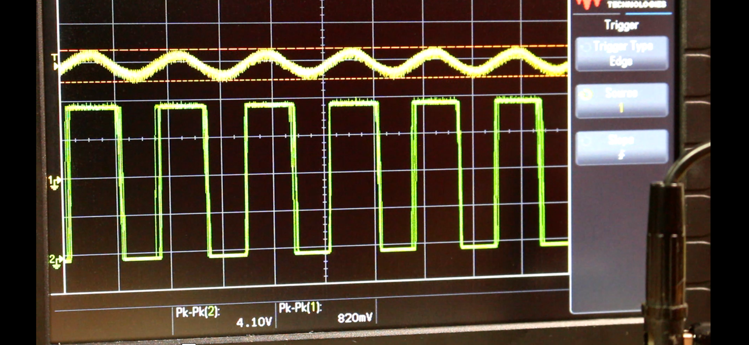
Ok so we have our signal amplified. The OPAMP configuration that we’ve used is an inverting one, that’s why the output signal is inverted as we can see in the photo above on my oscilloscope. When the input is positive the output is negative and vice versa. Also, we still have a sine wave. What I want is a square wave with the same frequency as this signal. So, for that I amplify the signal once again with the second amplifier and this will give me the square wave that I want. I connect the output from the first amplifier to the positive input of the second. The negative input of the second amplifier is connected once again to a potentiometer in order to set the middle voltage. This second configuration of the OPAMP is a comparator. It has infinite gain so we will have a positive pulse when the signal on the positive input is higher than the one set on the negative input and a low pulse when the input is below the set voltage on the negative pin.
I set the potentiometer to around 2.5V once again and observe the output on the oscilloscope. Great, I’ve got my square wave. As expected, I’ve got 5 volts when the input signal is above 2.5V and 0 volts when the input is below 2.5V. That gives me a square wave with the exact same frequency as the first input and that’s exactly what I wanted.
Before we go to the Arduino part I want to check my whistle frequency range. For that I place the frequency label on the oscilloscope and whistle from the lowest to the highest pitch that I can. My range is between 800Hz and 1600. But I’ve tried this test with a women whistle and I’ve reached up to 2500Hz so you should decide the range that you’ll use in the code.
Ok, we’ve got our detecting circuit ready.
Let’s go over the Arduino part.