This module for this post is a coin selector used for those redemption games machines. This can work with pretty much any type of metal coins all around the world. So how does it work? Inside we can see some infrared sensors, some copper coils, an electromagnet, operational amplifiers and a microcontroller. How can this module make the difference between several types of coins using those components? They are quite precise and the working principle is very interesting and involves magnetic disturbance. Well, in this post I will try to explain you how they work and make some homemade tests for each step. So, let's get started.
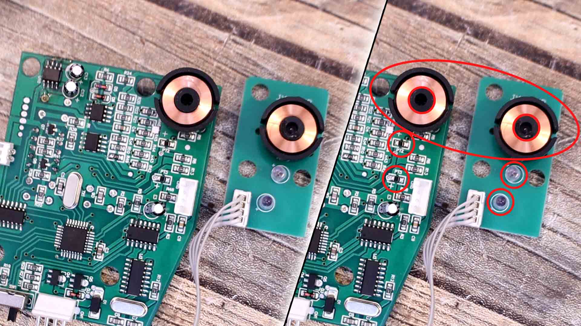
If we open this device we will see a few components. For example we can see a coil on one side and another coil just in fornt of ir on a separated smaller PCB. We can also see phototransistors and infrared LEDs face to face. We have 3 infrared LEDs and 3 phototransistors. On the PCB we have OPAMPs, a microcontroller and some voltage controllers for creatign engative pulses. On the other side of the main PCB we have that a smaller plastic case and inside it we have that other PCB with another coil and those 3 infrared LEDs. One LED is in the middle of the coil, in case you can’t see it. So basically these two PCBs are face to face and the coin will pass in between them. Inside the plastic case, the coin will enter through a small slot, it passes in front of some holes with the infrared LEDs. Then, on the big PCB inside we have those phototransistors. So, like that we can detect when the coin passes. Using these elements we can measure the speed of the coin, its diameter and its magnetic disturbance. With these 3 characteristics we can decide between several types of coins.
So we know that on the PCB we have some infrared sensors ina streight line. The coin will pass in between the sensors and create a digital pulse each time the coin is in front of the IR light. By measuring the time it takes the coin to pass between one infrared sensor and the next one, we can get the speed of the coin because we know the distance between the sensors. Sounds pretty easy to make this with Arduino, right?
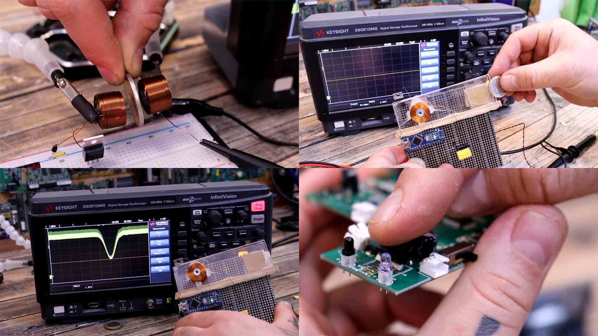
So lets start with the first element we need to measure, and that's the speed of the coin. For that we add two infrared light sensors separated a known distance in between, let’s say 2cm. So, for the test I’ve placed them face to face on a transparent plexiglass so we can see through it. As you can see, when I place the coin in front of the sensors, the signal goes HIGH. And in this case, yellow is for one sensor and the green line is for the other sensor. So now I roll the coin in front of both sensors. As you can see, we get two HIGH pulses. We can read these pulses with the Arduino and start a counter. The distance between the sensors divided by the time between these two pulses will give us the speed. In the below example the distacne is 2cm and the time btween pulses is 44. The speed is distance/time and we can store that on the Arduino memory and use it later.
If you think about it, two different coins could have the same speed because of their weight, but their diameter might be different, right?. So in order to have more precision and make a good difference between types of coins, we should also measure the diameter of the coin at the same time. So, on the other hand, to measure the diameter is even easier than measurign the speed, we only need one sensor. When the coin enters the sensor it will put the output HIGH and we start a counter. When the coin exits the same sensor, it will put the output back to LOW, and we detect that and we stop the counter. We multiply that time by the speed and we get the length of the coin, or the diameter in this case. We can do that very easy with the "pulsein" function of the Arduino. So we can use one of the previous pulses from the IR sensors and also measure the diameter of the coin.
By now we have the speed and the diameter using simple infrared sensors, but the final part is the most complicated one. How can we measure magnetic disturbance? We have two coils face to face. We pass some current pulses through one coil and it will create an oscillating magnetic field. As you can see on my oscilloscope, that induces a voltage in the second coil. But look in the example below, when I insert the coin in between, the amplitude of this signal drops. And this voltage drop value is different for each type of coin. So we might have a coin with the same speed, same diameter but they can be made of different materials, density of metals, etc. Different materials will create a different disturbance on the magnetic field so we can also record that value and with 3 properties, the decision precision will be a lot higher.
Well, I have a copper coil. Using a MOSFET and a PWM signal from the Arduino I apply pulses to this coil so it will create oscillating magnetic fields. Then I take a second coil and connect it to my oscilloscope. As you can see, the closer I get to the oscillating magnetic field, the higher will be the amplitude of the detected signal. I leave these coils face to face. Look, when I pass a coin between these coils, as you can see, the oscillation amplitude drops. That’s because some of the magnetic flux is lost inside the metal of the coin. Each coin could have a different metal, a different density or internal mixture, so this inductance drop would be different for each type of coin.
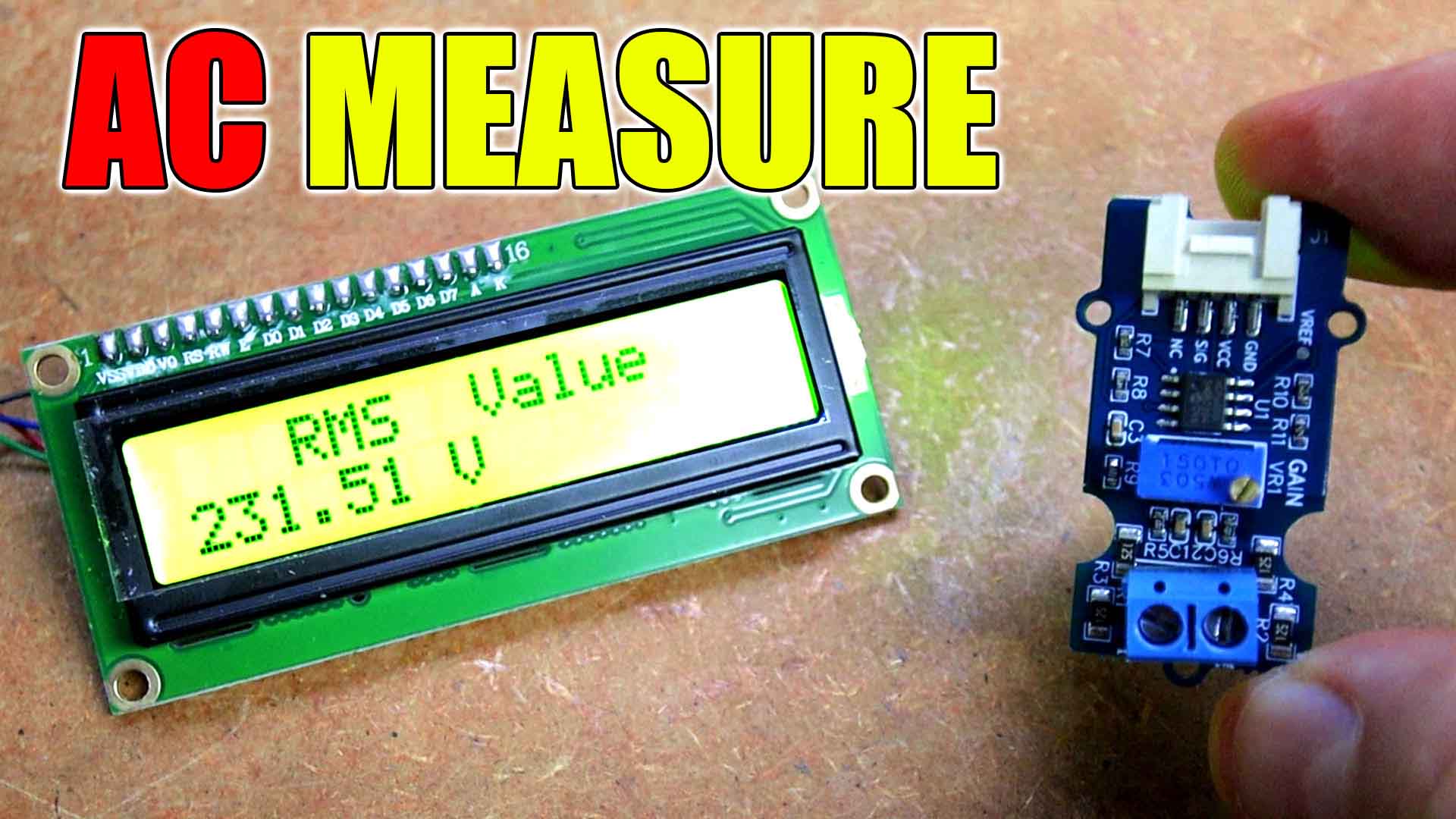
But how can we measure ths voltage drop with, for example, an Arduino? The signal is AC and the Arduino can't measure AC, especially when it is that fast. Well the first option is to add a capacitor at the output of the second coil. Since I have to try different values, I’ve made a PCB, and I can add different capacitors and test the results. When the coin passes between the coils, the oscillation amplitude drops, so the capacitor will create a peak. This peak will be different for each coin and since this is now DC, we can measure the minimum point with the Arduino. For example a coin created a minimum point of 2.23V as you can see below. But some other coin created a different peak with a minimum of 1.83V.
If this option is not good enough, we can also use an operational amplifier with an integral configuration. This should create the same result but maybe even better. And the third option would be to use a hall sensor but those might be a bit too slow. So for each coin we create a table with 3 values. Speed, diameter and the voltage measured from the magnetic disturbance. To get even more accurate results, remember that with the commercial selector, we first measure the same type of coin 20 times and then we create the mean of those 20 measurements.
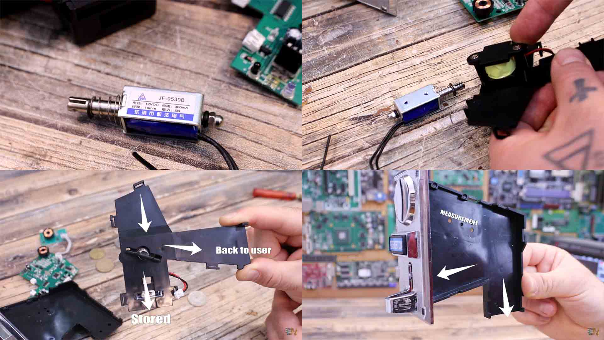
Finally, to count the amount of coins, at the output, the commercial coin detector has one more infrared sensor. Like that, when the coin passes in front of these two holes, it will be detected. This will make sure that the coin will exit the counter, otherwise there might have been a problem inside. As for the electromagnet, it is something like this one below. Applying 5V we can make it push the piston out. With that we can change the trajectory of the coin and make it go inside the machine or back to the user.
So that’s basically how a coin selector like this one works and they could get quite precise. I haven't made the entire homemade version because it is too time consuming. But now that I’ve shown you how to make all 3 parts, you could probably try making one yourself if you want. But anyway, the commercial one is only 20 dollars so I don’t think that a homemade one makes sense. I hope that you have learned something new. If my videos help you, consider supporting my work on my PATREON or a donation on my PayPal. Thanks again and see you later guys.