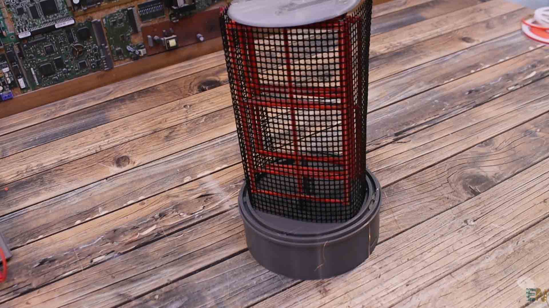
Hi guys. This here is a huge and homemade nixie tube. We all know that usually nixie tubes are small, just a few cm, right? A big nixie tube could get very, very expensive. That’s why I’ve made my own using a flexible LED strip with close enough color and glow as a nixie tube would have. Looks quite nice, right? So guys let me show you how I’ve made the design, what type of LED strip I’m using, how to make the connections and what components we need in order to make this project. So stick till the end if you want to see how this works. So, let’s get started.
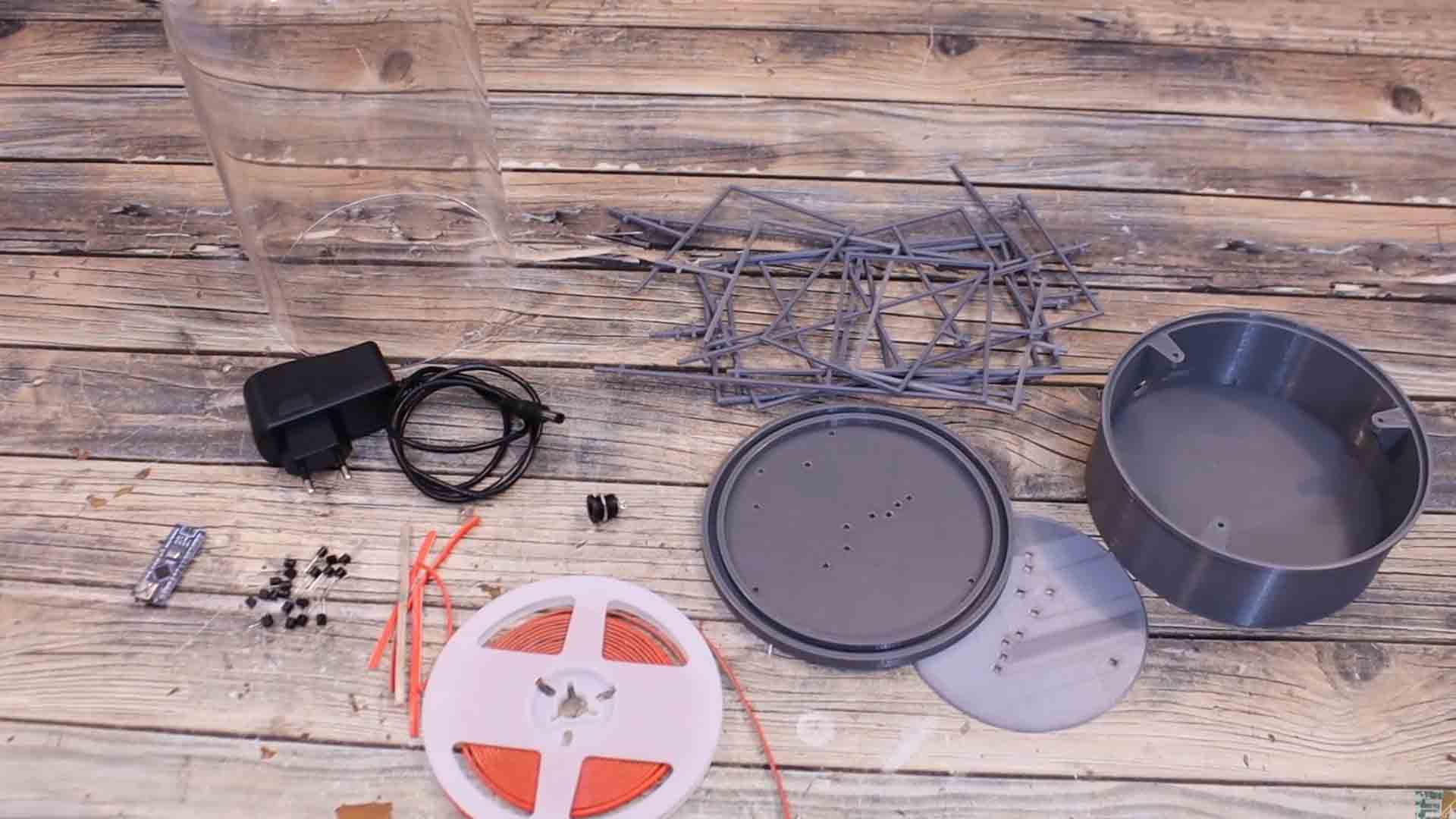
What’s up my friends, welcome back to another tutorial. One of the main parts for this project is the glass cylinder that will give the nixie tube look. I’ve bought mine from IKEA and I’ll put that link below but I’m not sure if they ship world wire. That’s why I will also place some AliExpress links for some similar glass tubes. Mine has 14 cm diameter and is around 25cm tall. Is important to know its exact size in order to be able to design the 3D part. That part will go below the tube and will support the segments. Then we need the LED strip, a plastic dark mesh, some BJT transistors, an Arduino NANO and some wires. Also have some tools and glue around. Check full list below.
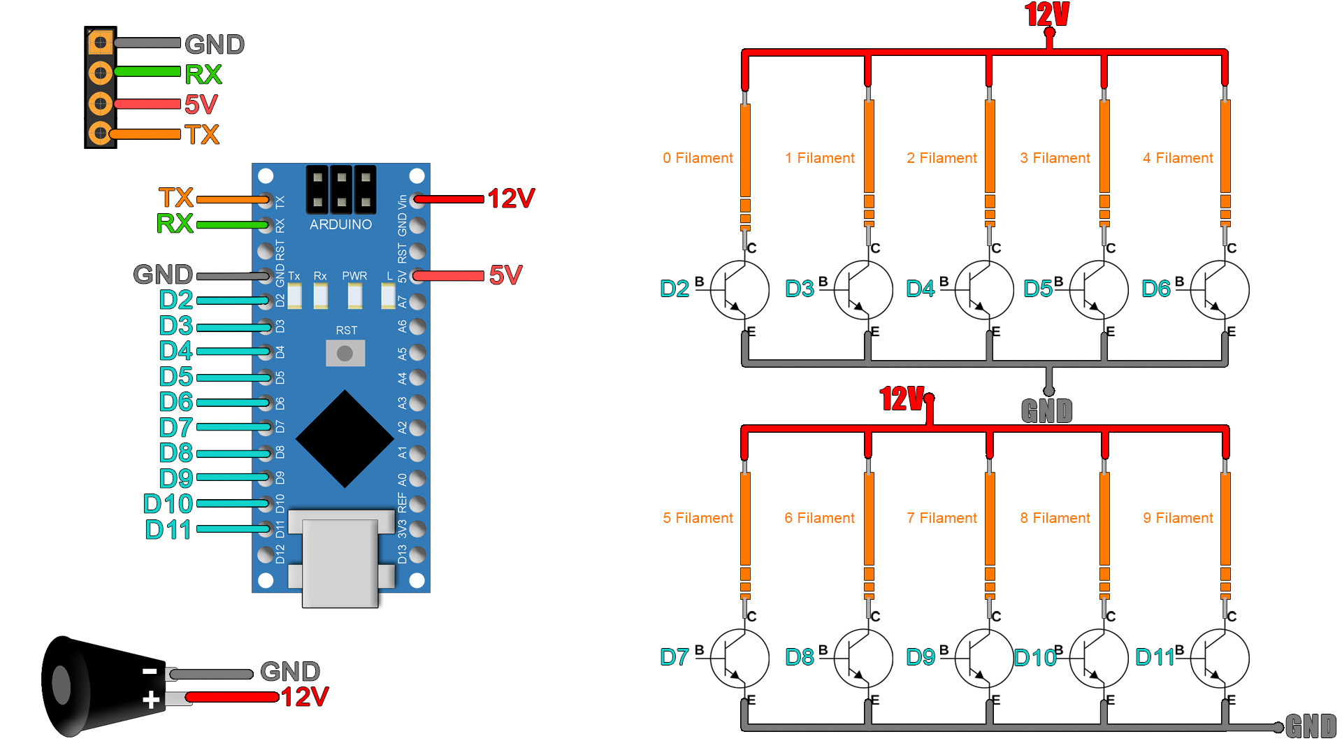
The connections are more than easy. Connect each LED filament with positive to 12V and the negative part of the LED is connected to the collector of the S8050 NON transisitor. The transistor is then connected to ground and using a pin from the Arduino for each BJT, we can control when to turn on and off each filament. The Arduino is supplied with 12V from the DC adaptor and it can create 5V because it has its own regulator. We also add 4 female pins for the serial communication between the master Arduino and the controller Arduino of the display.
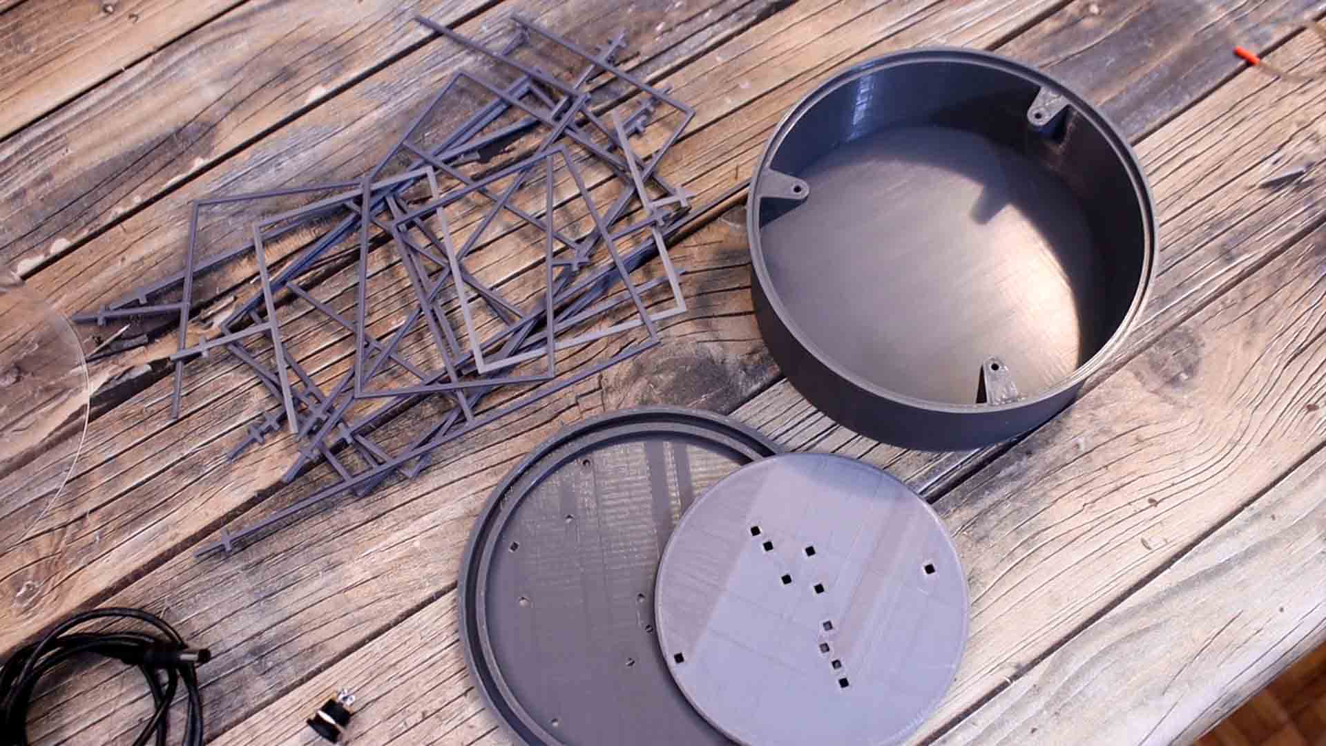
The next part we need for this project are the 3D printed segments, one for each number. These were designed to be only 1.5mm width and on top of these supports we will add the LED strip which is the next component that we need. We also need the top support of the segments and the bottom case. Inside that case is where all the electronics will go. So, download my design from below and 3D printed. I’ve used PLA material for all the parts. If you use a different size glass tube, you will need to change the 3D design to fit your tube. You can also find my files HERE
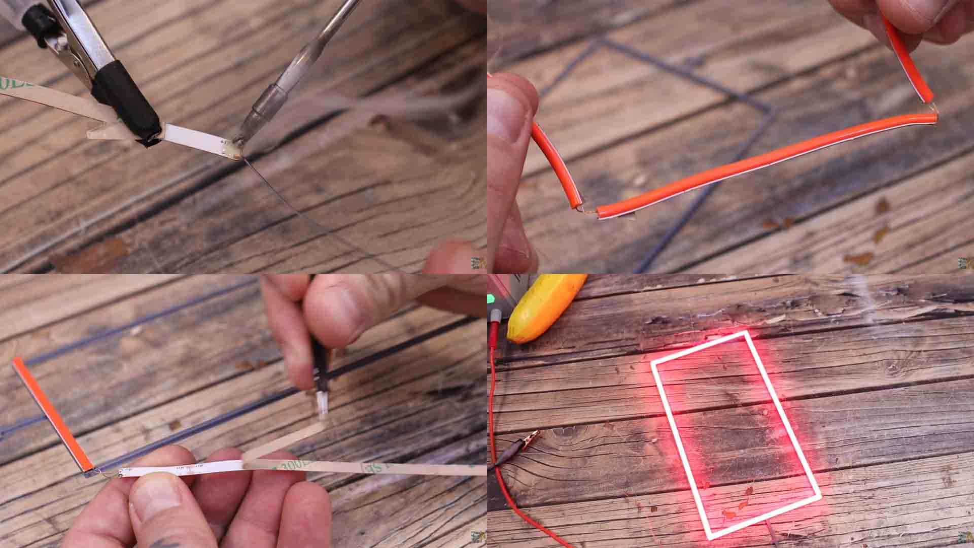
Ok, so let’s start. Now get each number and the LED strip. Let’s start with the 0. We need to cut 2 parts of 4 segments of LED and two more parts of 7 segments. The strip has glue on the other side so is easy to glue in place. But first we need to solder thin wires for 12V and ground. So, on the small pads on the back side of the strip solder thin wires. Then we merge the strips together so power from one will go to the next. The first segment must have longer wires, because that will be connected to the transistors inside the electronics case. Once you have the wires, fully peal the protection on the back of the strip and glue the segments on the plastic support. And just like that, we have our first number. Let’s light it up. You can see that it mimics a little bit the color and the glow of a nixie tube number.
Then we do the same for all the numbers making sure we add the wires and we glue the segments in the correct position. After a while I finally have all the numbers from 0 to 9. Is time to add the top and bottom support. We start with the bottom support so it will keep the numbers in place. Make sure you pass the wires to the inside side of the case. Then push the number inside the support. Once we have all the numbers, we add the top support and also add a little bit of glue. Be careful not to break any of the segments or wires. Now all the numbers are in place.

We could now cover the support with the glass tube. But before I do that, I also want to add a dark mesh. I’ve bought a dark mesh so we could create a better background. If you look at real nixie tubes, you will see that the numbers are enclosed inside a metal mesh. I cut that to size and somehow, I try to fix it in place around the numbers. Now we can add the top glass tube. I add just a little bit of hot glue inside the plastic support and then I add the tube. Like that, the glass will have a little bit of grip and stay connected to the support. Is time for the electronics.
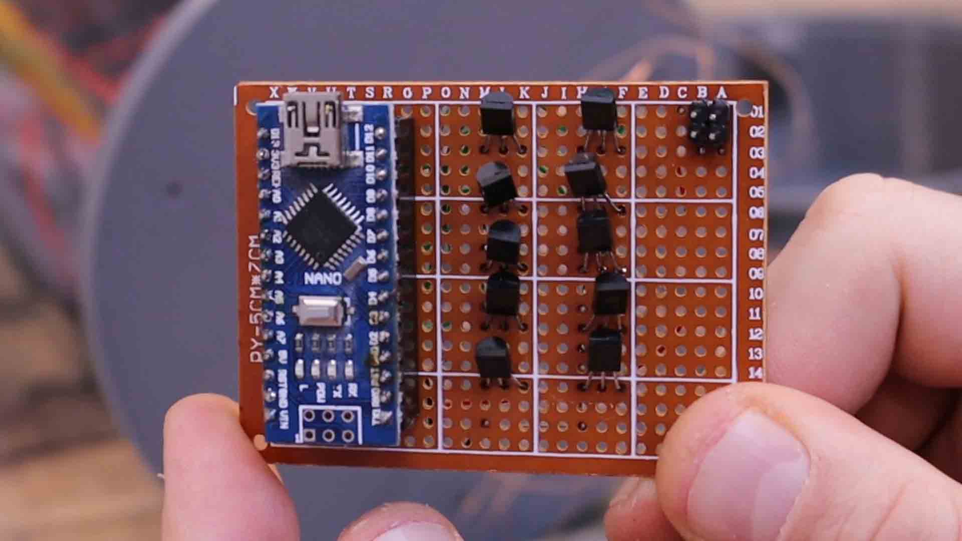
On a piece of prototyping PCB I solder the Arduino. Then I add 10 transistors. I make connections from the digital pins of the Arduino to the base of each transistor. Check the schematic above. I connect each transistor with the emitter to ground and the collector will go to the negative side of each LED. The other wire of the LED will go to 12V. So I make all the wire connections to the PCB and I merge together all the 12V wires. For 12V I have this jack connector and the plastic case has a hole on the back. I solder two wires to the jack, I add it to the case and tight the screw. These wires will be connected to the PCB as in the schematic. I also solder thin wires to some female pins. I solder them to the Arduino UART port. Then I glue those pins on the back part of the case as well. I use these pins to control more nixie tubes using serial communication.
The idea is to connect more nixie tubes like this one in series. Let’s say that we have 3 and we want to display a 1, a 5 and a 7. From the control Arduino I would send a 751 to the data in pin. The first Arduino will store the 1 and send on the data out pi a 75. The second Arduino will store the 5 and send the 7. This process could be repeated for any amount to nixie tubes.
In the code we define all segments as OUTPUTS and set them to low. If we detect a serial input, we store the first value corresponding to the first nixie tube. Then we store the other values and we send them out on the data out pin. With the display number function, first we check which number was received from 0 to 11. We go to 11 because we need numbers from 0 to 9 but also to know when the nixie is fully off. According to these numbers, we light up one or other number and that’s it.
// Include the required Wire library for I2C
#include <Wire.h>

int LED0 = 2;
int LED1 = 3;
int LED2 = 4;
int LED3 = 5;
int LED4 = 6;
int LED5 = 7;
int LED6 = 8;
int LED7 = 9;
int LED8 = 10;
int LED9 = 11;
int x = 0;

byte data_in[1];
byte data_out[1];
bool first_byte = false;

void setup() {
  pinMode(LED0, OUTPUT);
  pinMode(LED1, OUTPUT);
  pinMode(LED2, OUTPUT);
  pinMode(LED3, OUTPUT);
  pinMode(LED4, OUTPUT);
  pinMode(LED5, OUTPUT);
  pinMode(LED6, OUTPUT);
  pinMode(LED7, OUTPUT);
  pinMode(LED8, OUTPUT);
  pinMode(LED9, OUTPUT);

  digitalWrite(LED0, LOW);
  digitalWrite(LED1, LOW);
  digitalWrite(LED2, LOW);
  digitalWrite(LED3, LOW);
  digitalWrite(LED4, LOW);
  digitalWrite(LED5, LOW);
  digitalWrite(LED6, LOW);
  digitalWrite(LED7, LOW);
  digitalWrite(LED8, LOW);
  digitalWrite(LED9, LOW);
  Serial.begin(9600);
}
void loop() {
  if (Serial.available()) {
    if (!first_byte) {
      Serial.readBytes(data_in, 1);
      first_byte = true;
      display_number(data_in[0]);
      //Serial.println(data_in[0]);
    }
    else {
      Serial.readBytes(data_out, 1);
      if(data_out[0] == 12){            //12 is the stop number
        first_byte = false;
      }
      else{
        Serial.write(data_out[0]);
        //Serial.println(data_out[0]);

      }
    }
  }//End of serial available


}//End of void loop


void display_number(int number) {
  if(number == 11){                 //ALL OFF
    digitalWrite(LED0, LOW);
    digitalWrite(LED1, LOW);
    digitalWrite(LED2, LOW);
    digitalWrite(LED3, LOW);
    digitalWrite(LED4, LOW);
    digitalWrite(LED5, LOW);
    digitalWrite(LED6, LOW);
    digitalWrite(LED7, LOW);
    digitalWrite(LED8, LOW);
    digitalWrite(LED9, LOW);
  }

  if(number == 0){                  //0 is ON
    digitalWrite(LED0, HIGH);
    digitalWrite(LED1, LOW);
    digitalWrite(LED2, LOW);
    digitalWrite(LED3, LOW);
    digitalWrite(LED4, LOW);
    digitalWrite(LED5, LOW);
    digitalWrite(LED6, LOW);
    digitalWrite(LED7, LOW);
    digitalWrite(LED8, LOW);
    digitalWrite(LED9, LOW);
  }

  if(number == 1){                  //1 is ON
    digitalWrite(LED0, LOW);
    digitalWrite(LED1, HIGH);
    digitalWrite(LED2, LOW);
    digitalWrite(LED3, LOW);
    digitalWrite(LED4, LOW);
    digitalWrite(LED5, LOW);
    digitalWrite(LED6, LOW);
    digitalWrite(LED7, LOW);
    digitalWrite(LED8, LOW);
    digitalWrite(LED9, LOW);
  }

  if(number == 2){                  //2 is ON
    digitalWrite(LED0, LOW);
    digitalWrite(LED1, LOW);
    digitalWrite(LED2, HIGH);
    digitalWrite(LED3, LOW);
    digitalWrite(LED4, LOW);
    digitalWrite(LED5, LOW);
    digitalWrite(LED6, LOW);
    digitalWrite(LED7, LOW);
    digitalWrite(LED8, LOW);
    digitalWrite(LED9, LOW);
  }

  if(number == 3){                  //3 is ON
    digitalWrite(LED0, LOW);
    digitalWrite(LED1, LOW);
    digitalWrite(LED2, LOW);
    digitalWrite(LED3, HIGH);
    digitalWrite(LED4, LOW);
    digitalWrite(LED5, LOW);
    digitalWrite(LED6, LOW);
    digitalWrite(LED7, LOW);
    digitalWrite(LED8, LOW);
    digitalWrite(LED9, LOW);
  }

  if(number == 4){                  //4 is ON
    digitalWrite(LED0, LOW);
    digitalWrite(LED1, LOW);
    digitalWrite(LED2, LOW);
    digitalWrite(LED3, LOW);
    digitalWrite(LED4, HIGH);
    digitalWrite(LED5, LOW);
    digitalWrite(LED6, LOW);
    digitalWrite(LED7, LOW);
    digitalWrite(LED8, LOW);
    digitalWrite(LED9, LOW);
  }

  if(number == 5){                  //5 is ON
    digitalWrite(LED0, LOW);
    digitalWrite(LED1, LOW);
    digitalWrite(LED2, LOW);
    digitalWrite(LED3, LOW);
    digitalWrite(LED4, LOW);
    digitalWrite(LED5, HIGH);
    digitalWrite(LED6, LOW);
    digitalWrite(LED7, LOW);
    digitalWrite(LED8, LOW);
    digitalWrite(LED9, LOW);
  }

  if(number == 6){                  //6 is ON
    digitalWrite(LED0, LOW);
    digitalWrite(LED1, LOW);
    digitalWrite(LED2, LOW);
    digitalWrite(LED3, LOW);
    digitalWrite(LED4, LOW);
    digitalWrite(LED5, LOW);
    digitalWrite(LED6, HIGH);
    digitalWrite(LED7, LOW);
    digitalWrite(LED8, LOW);
    digitalWrite(LED9, LOW);
  }

  if(number == 7){                  //7 is ON
    digitalWrite(LED0, LOW);
    digitalWrite(LED1, LOW);
    digitalWrite(LED2, LOW);
    digitalWrite(LED3, LOW);
    digitalWrite(LED4, LOW);
    digitalWrite(LED5, LOW);
    digitalWrite(LED6, LOW);
    digitalWrite(LED7, HIGH);
    digitalWrite(LED8, LOW);
    digitalWrite(LED9, LOW);
  }

  if(number == 8){                  //8 is ON
    digitalWrite(LED0, LOW);
    digitalWrite(LED1, LOW);
    digitalWrite(LED2, LOW);
    digitalWrite(LED3, LOW);
    digitalWrite(LED4, LOW);
    digitalWrite(LED5, LOW);
    digitalWrite(LED6, LOW);
    digitalWrite(LED7, LOW);
    digitalWrite(LED8, HIGH);
    digitalWrite(LED9, LOW);
  }

  if(number == 9){                  //9 is ON
    digitalWrite(LED0, LOW);
    digitalWrite(LED1, LOW);
    digitalWrite(LED2, LOW);
    digitalWrite(LED3, LOW);
    digitalWrite(LED4, LOW);
    digitalWrite(LED5, LOW);
    digitalWrite(LED6, LOW);
    digitalWrite(LED7, LOW);
    digitalWrite(LED8, LOW);
    digitalWrite(LED9, HIGH);
  }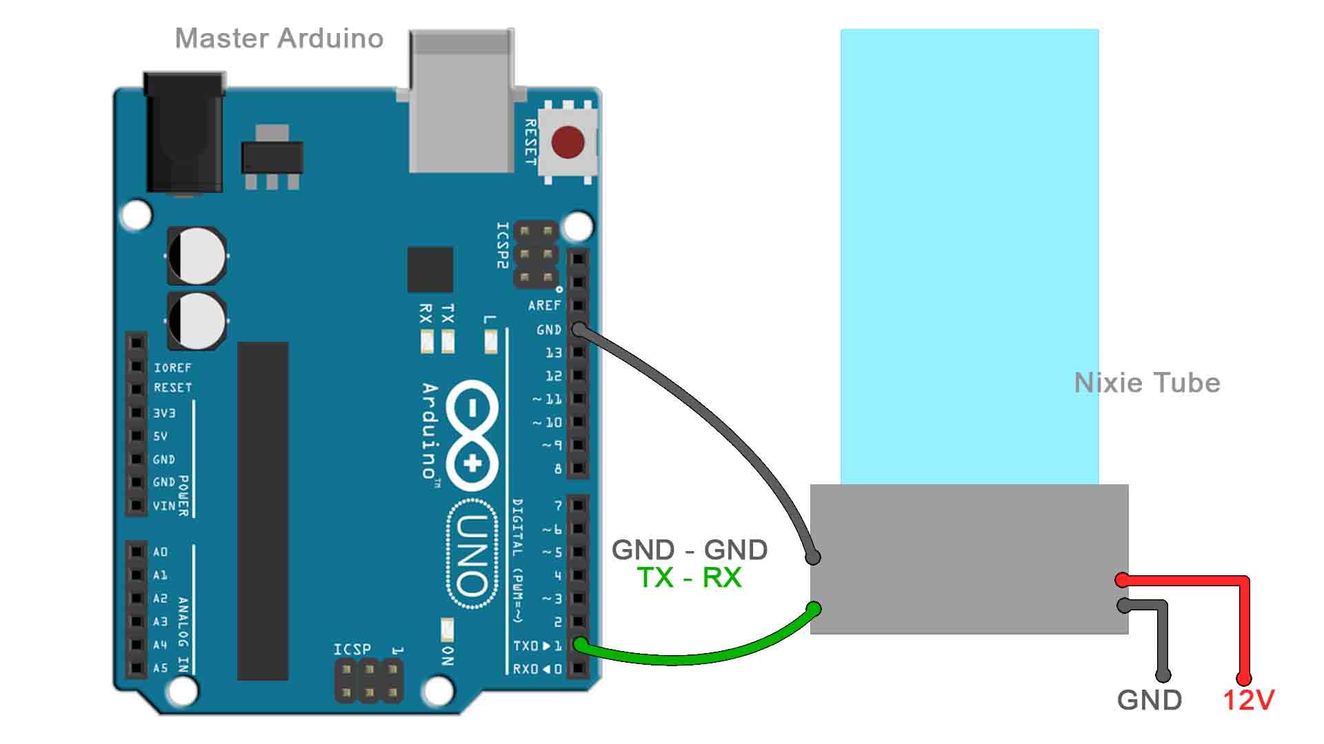
}Download the RX code from above and upload it to the Arduino NANO of the nixie tube. The code is made in such a way that we could control the numbers using another Arduino and serial communication. I connect an external Arduino to the ground and data in pin and upload the TX code to it. Connect the master Arduino as below. I connect 12V to the nixie tube from the DC adaptor. I supply the external Arduino with a USB cable and this will send instructions for numbers from 0 to 9 and there you have it. It looks pretty nice, right? And quite close to a real nixie tube? What do you think?
The fact that is huge, in my opinion, makes this project be a lot more interesting. Usually nixie tubes are small, just a few cm tall. But this one has 25cm height. Also, having the serial communication, is very easy to control more than just one nixie tube. We can add any amount of tubes and control them in series.
So guys, if you want to make the same or maybe improve this project, you have all my designs and the schematic above. If my videos help you, consider supporting my work on my PATREON or a donation on my PayPal. Thanks again and see you later guys.