Hey guys. I know there are already a lot of balancing robot projects on the internet, but I wanted to make one as well. Actually, I wanted to make something special and make a mini balancing robot, but I kind of failed with the stepper motors and I will explain the problem in the video below. So what I’ve done in the end, is to use the same PCB I’ve prepared for a mini balancing robot, design a small 3D printed body and use bigger stepper motors and like that be able to finish my idea. The robot should get information from a homemade remote with Bluetooth connection and like that we could move around. But internally, the robot should also get information from an IMU module and calculate a PID value of the angle so it will never fall and always try to stay horizontal. That’s pretty interesting and I think you will learn a lot with this project because I will explain each step of the circuit but also the code. So what do you think, will this work? So let’s get started.
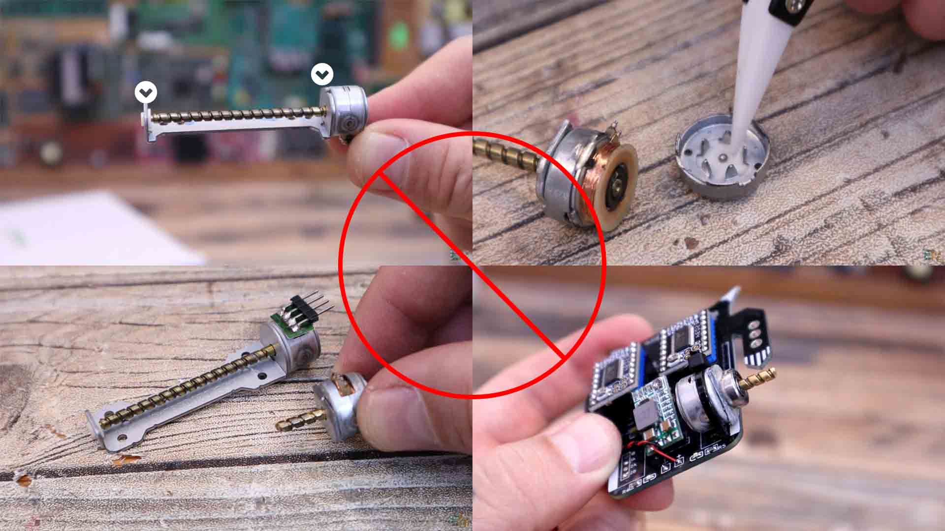
My plan was to use the PCB of this project with this kind of stepper motors you can see below. I have these from old DVD writers and I thought they would work great connected to my PCB. Is very easy to control them with some stepper drivers so that’s not the problem. The problem was mechanical. You see, these motors have a shaft connected to the magnets inside. This shaft is supported on both sides. In order to add a wheel to this shaft, I had to cut it smaller, and in that way, we have support only on one side, and that’s the problem. Without support on both sides, this shaft will move around and automatically break all the small coils and magnets inside. I’ve tried gluing a bearing at the output but without success. Inside, the shaft is kept in the center by a metal ball, and once you move that, you can say goodbye to the hole motor. So I had no other option but to use NEMA 17 motors. So, on the side of the PCB I’ve designed a 3D printed support.
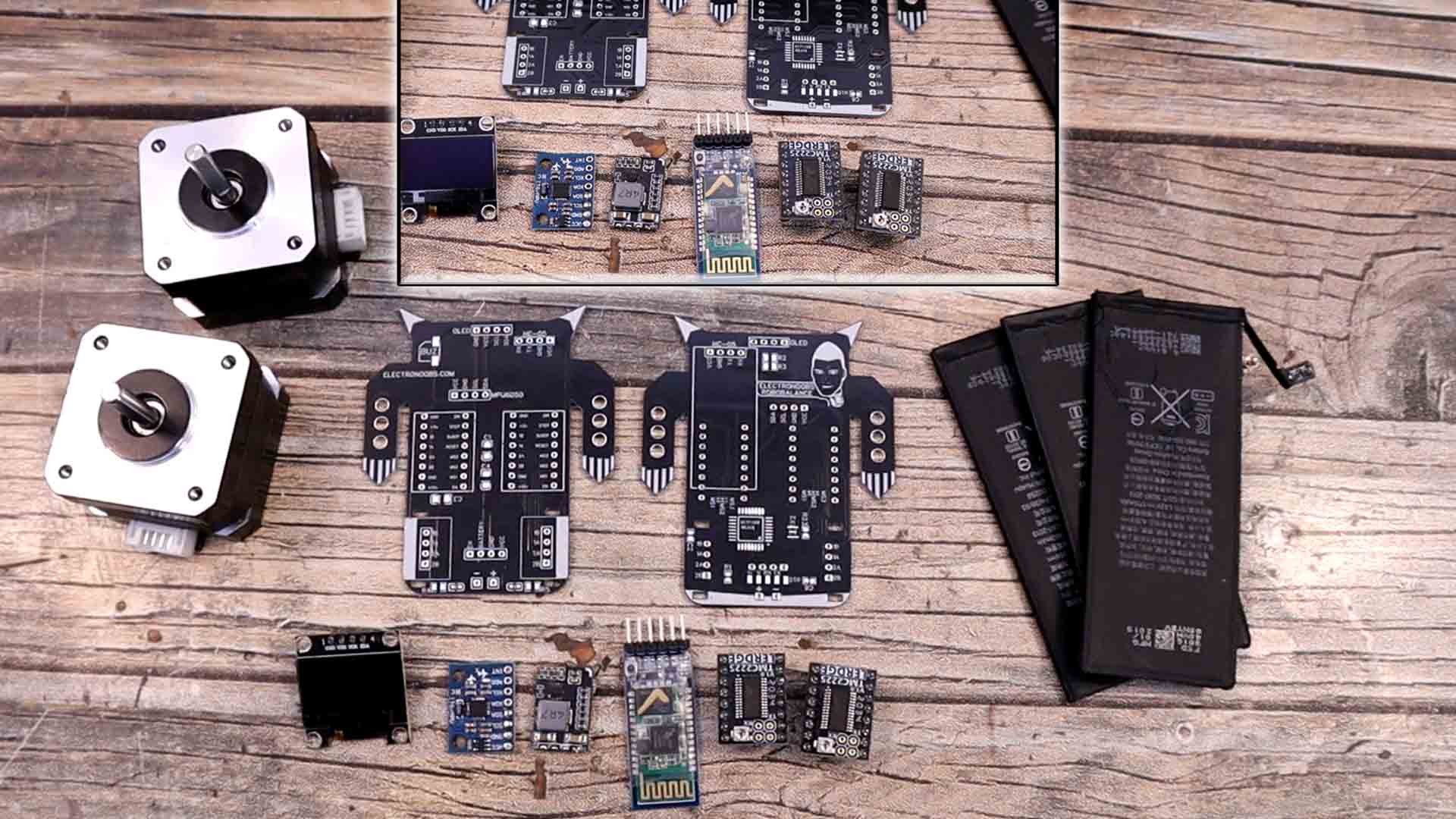
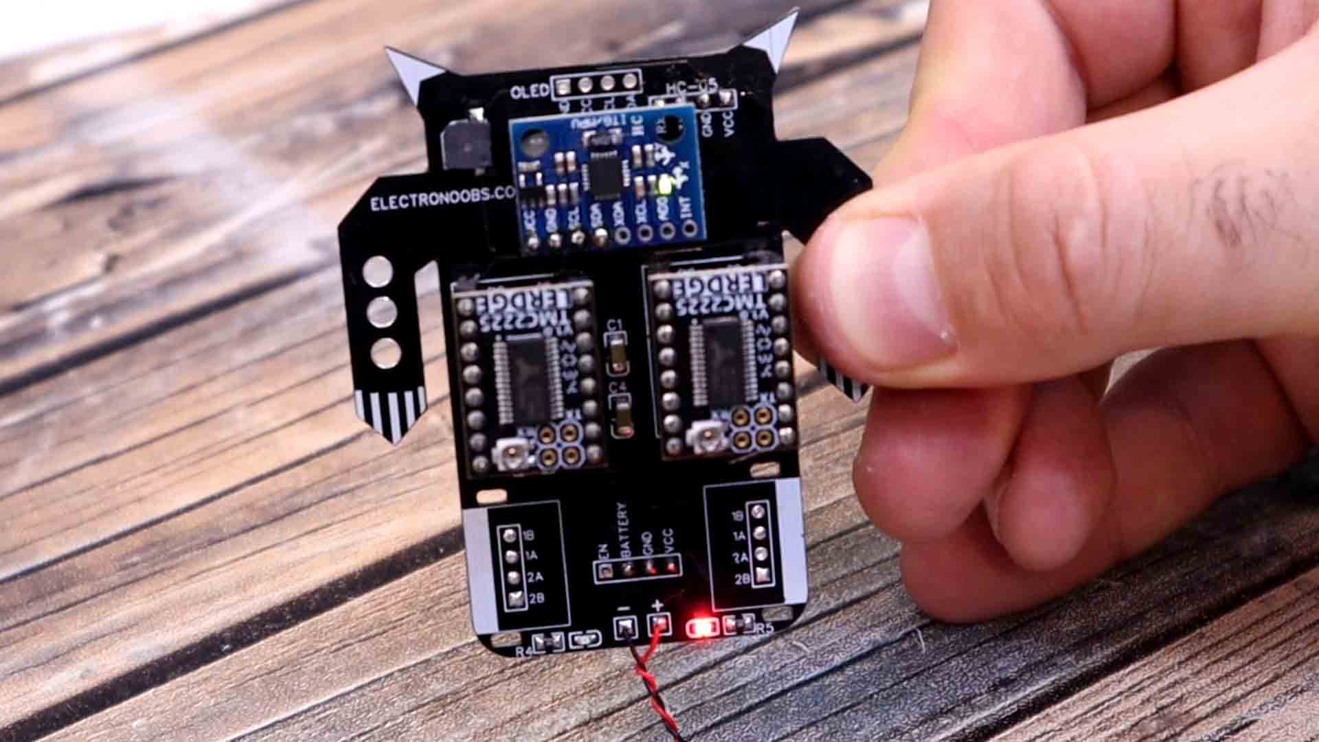
Let's see what we need for this project. First, the PCB. If you want the same PCB, get the GERBER files from a chapter below and go to PCBWAY and order the boards. The list is not that long. We need the stepper drivers which could be the basic A4988 but even better, the TMC2225 drives for a better and silent movement. We need two NEMA 17 motors, the MPU6050 gyro/acc module, a small 5V buck converter, a 3S battery, two HC-05 Bluetooth module, one for the robot and another one for the remote. Extra, we could also add a small OLED screen in order to create faces for the robot. As small aprts, we need an ATMega328p-AU chip, the 16MHz resonator and some SMD resistors and capacitors. Also a small SMD Buzzer and some LEDs.
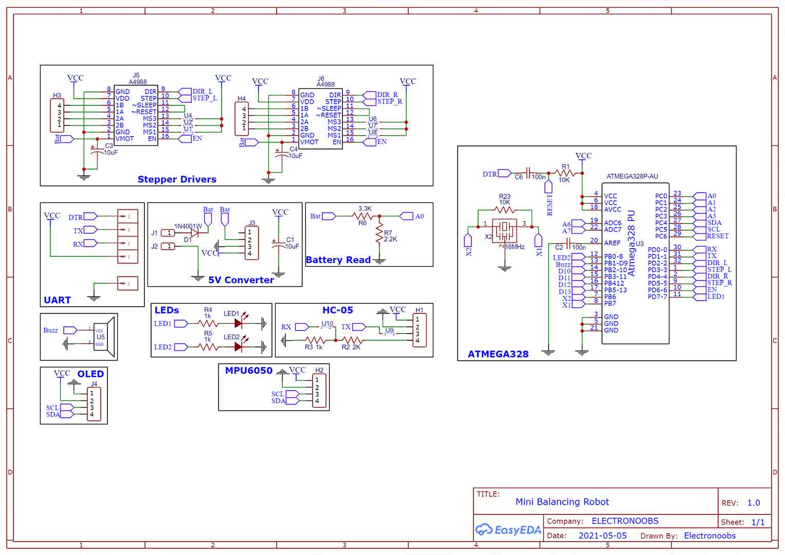
The schematic for the PCB is below. The battery, the main ON and Off switch and the motors are connected externally. Make sure you connect the NEMA 17 motor with conenctiosn in this order: 1B 2A 1A 2B. The rest of the connections are made on the PCB. The Buck converter is also external so make sure you connect in the right way. Make sure is fiexd at 5V.
So, let’s see what we have on the PCB. If you want the same PCB, get the GERBER files from below and go to PCBWAY. Click quote now and select your settings such as thickness, amount of PCB, materials and the solder-mask color. In my case I’ve selected black but you can select any other, they now have purple or mate black which look amazing. On the next page upload the GERBER zip file and order the PCBs. I’ve received the PCBs to Spain in around 8 days so check them out in the picture below.
Download the schematic from above and have it in front of you. I first soldered the SMD capacitors, resistors snd the ATMega328 chip on the back together with the 16MHz resonator and the 100nF C6 capacitor. Then I’ve added some female pins for the drivers so I can remove them if I want. I get one of these small buck converters and solder the 5V connection on the back. I connect it to 12V and test if the output is around 5V. Now we could solder this to the PCB but we will do that later.
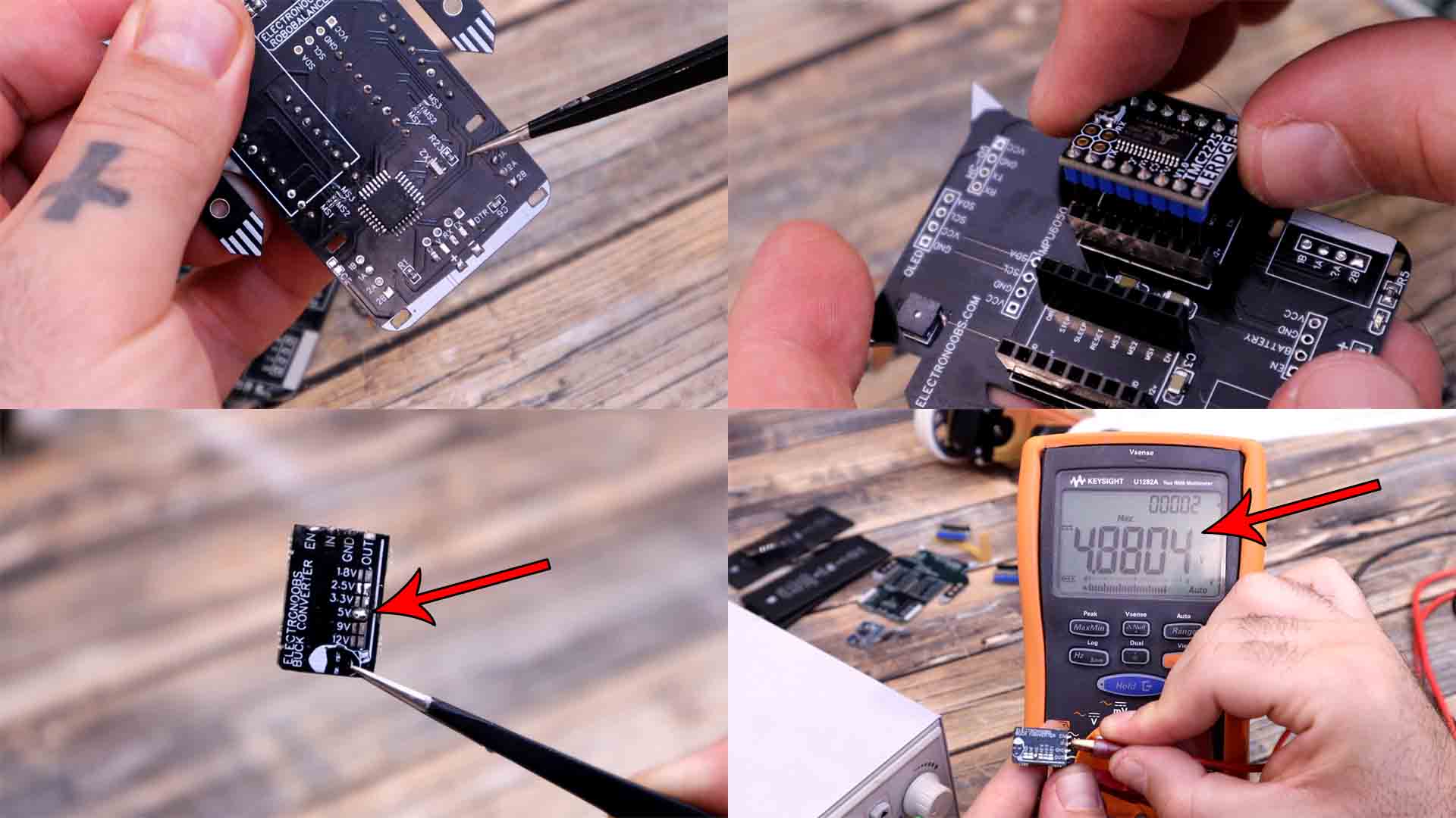
I also solder the buzzer top of the PCB, and the LEDs on the bottom. At this point I connect and FTDI programmer and test the connection to make sure it works. On the front side, I solder the MPU6050 accelerometer as well. On the back, I connect female pins for the Bluetooth module. Now that the ATMEGA chip is in place and it works, I can solder the buck converter on top so we can supply the PCB with a battery.
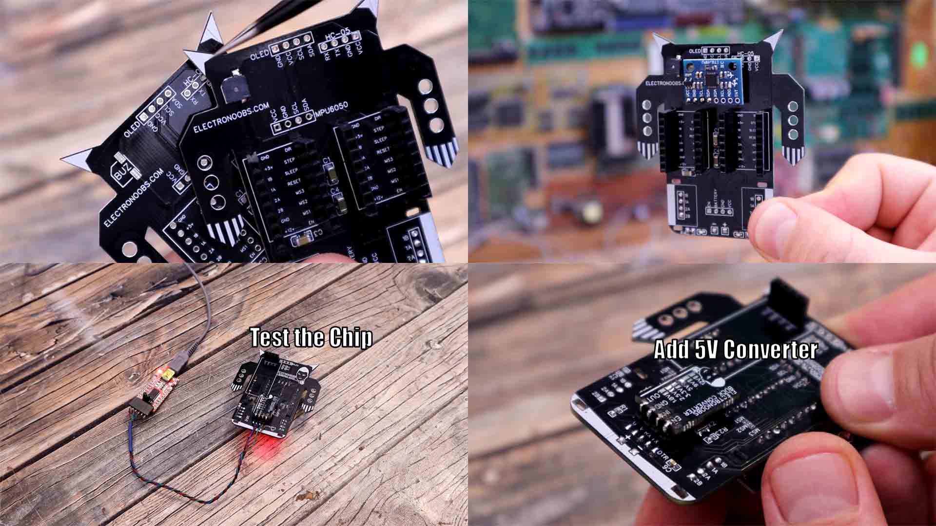
I might add the OLED screen later when everything works. Please check this full schematic for all the connections if you’re trying to make the same project. Remember to also solder together the small pads for MS2 on the back in order to enable quarter micro stepping. At this point you could download the code from a chapter below and upload it to the PCB using the FTDI programmer. We now have to connect the PCB to the motors and the battery.
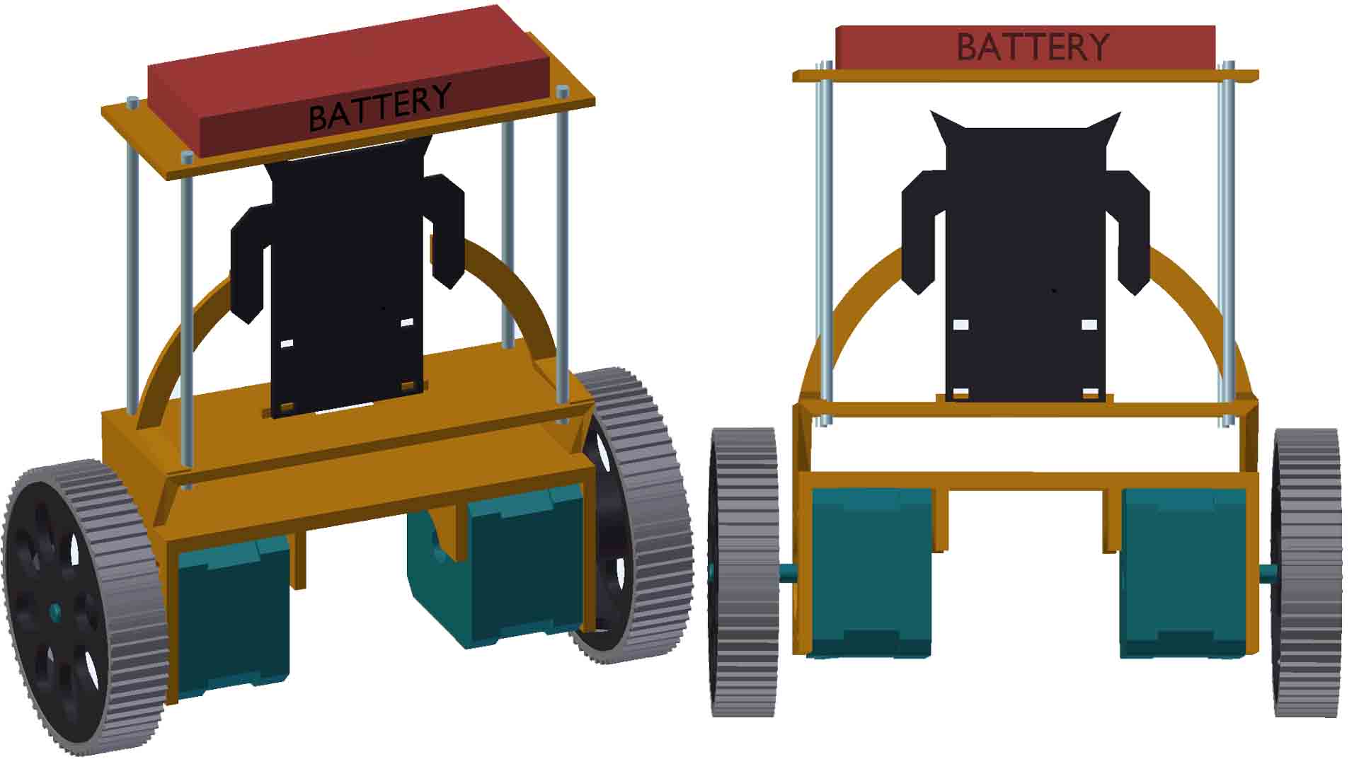
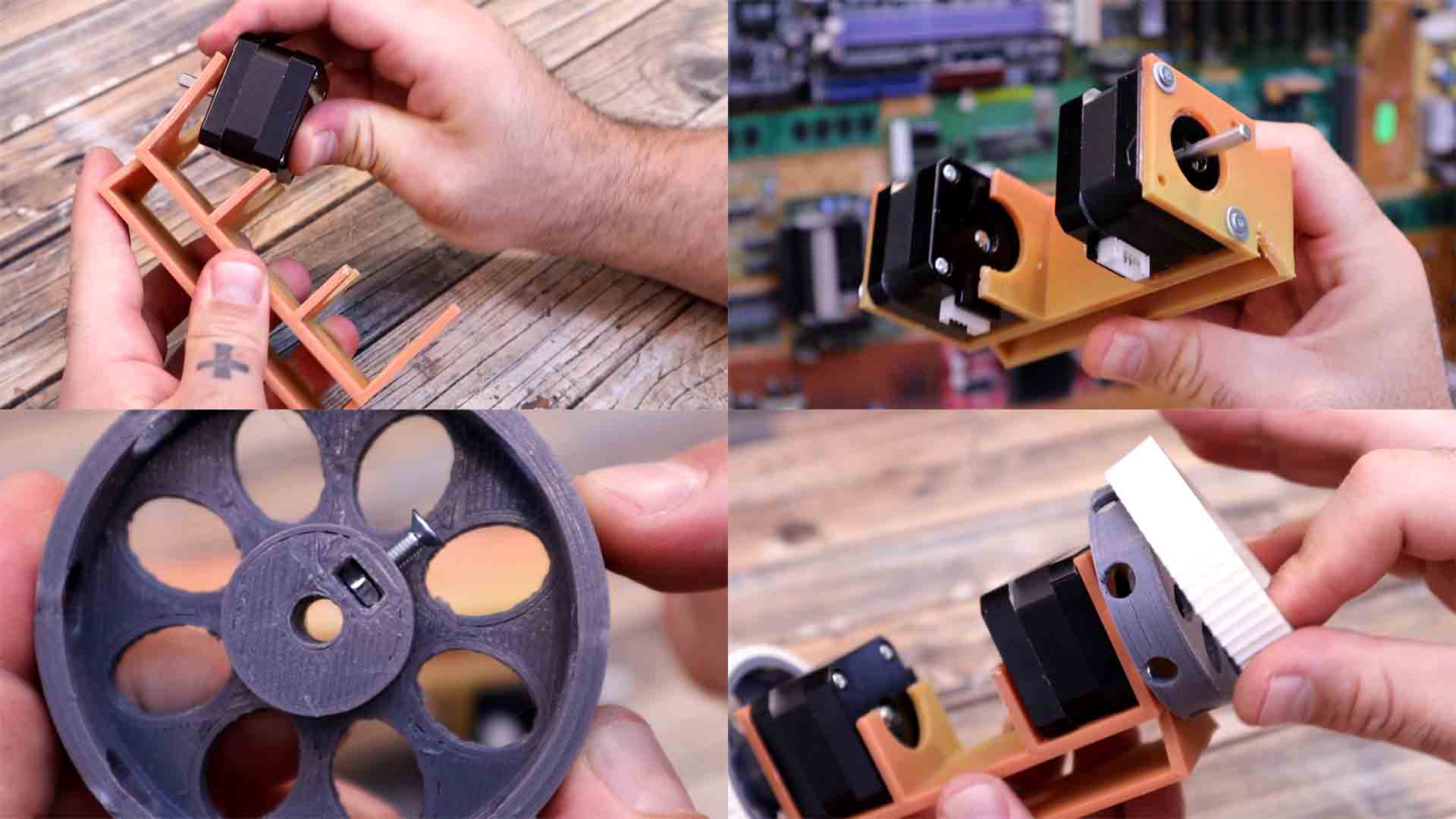
For the body, just download the STL files from below and print them with PLA material. I’ve used a 0.2mm layer height and 0.4mm nozzle with 3 perimeters and 20% infill. As for the wheels, the inner part is made out of PLA but the exterior is made out of flexible a material that must be printed at lower speeds. Like that we can have more grip. The wheels have holes so I can pass a screwdriver and tight a screw. We have to add a screw nut and then insert the shaft of the motor and tight that screw. Like that it will stay in place. Then we can add the rubber part on top.
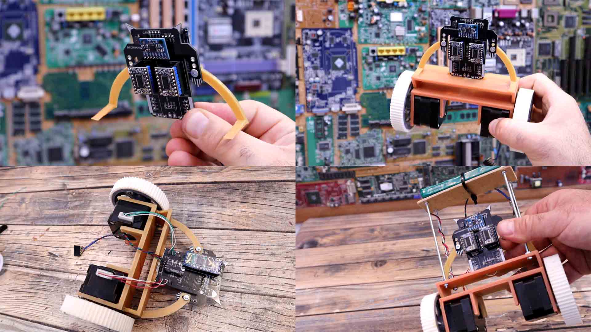
I get the main 3D printed part and I add the step motors. You just have to apply a little bit of force and it will snap into place. Then we add some screws and washers and tight the motors in place. Make sure the motor connector is on the back side of the motor. Get the plastic wheels and add a small nut inside the shaft hole. Also add a screw. Now add one wheel to each motor. Tight that screw so it will stay tight on to the motor shaft. This part was printed in flexible filament. We can add this part on top of the wheel.
Get a plastic printed leg and screw it on one arm of the PCB and do the same with the other side but don’t tight the screws yet. Place the PCB over the main body and glue in place the small plastic arms. Now we can tight those screws and the PCB is fixed in place. Solder wires from the stepper motors to the PCB in this order: 1B 2A 1A 2B. Between the battery and the PCB I add a switch so I can turn it ON and OFF. I’ve placed some threaded rods on top of the robot. And on top I have a plywood part (or the 3D printed plate) and here I will now place the battery. Like this we have more inertia when moving.
The code is almostthe same as we had for the brushless PID controller or the ping pong ball controller, but this time we use stepper motors. Top create the step pulses applied to the stepper drivers, we use a timer, TIEMR 2 in this case. By setting some registers, we make that timer to click every 20us. We read the raw data from the gyro and accelerometer. To overcome the gyro offset, at the begginning, we make around 500 reads from the IMU module and save that data as offset and subtract it later in the main loop. Then we calculate the angle each loop which is set to be each 4000us. Using the "gyro_angle" variable, we can calculate the PID value. As always, we find the PID error which is the difference between the real angle of the robot and the desired angle, which should be 0 so the robot would stay horizontal. Finally, inside the timer routine, depending on the PID output, we calculate the speed of the motors by creating more or less, faster or slower pulses applied to the stepper motors. To make the code faster, instead of digital read we use register control where this line for example: PORTD |= 0b00001000; is the same as setting the digital pin D3 to HIGH. For more about this, take a look at my Arduino register control video.
My robot is still wobbling around a little bit. That’s because we have to adjust the PID values in the code. This was the longest part of this project. I had to manually go and change the PID values till I got better results and even so, I’m not quite happy with the final results. If you start only with P values and the I and D are 0, you get some kind of oscillations where the wheels are rotating in the same direction as the tilt of the robot according to the angle. Then we add some D values and it will react to the speed of changing of the angle, and try to stop the oscillation, but that's not enough when the error is very small. Finally, to fine adjust the position, we add the I that will increase or decrease slowly when the error is small.Aftter more than 30 tries, I've got more or less good results and the robot is quite stable but I'm not entirely happy yet.
/////////////////////////////////////////////////////////////////////////////////////////////////
///////////////////////////////////////////PID VALUES////////////////////////////////////////////
/////////////////////////////////////////////////////////////////////////////////////////////////
float Kp = 30;                    //P Gain; Mine was 30
float Ki = 0.61;                  //I Gain; Mine was 0.61
float Kd = 9;                     //D Gain; Mine was 9
float Moving_Speed = 20;          //Moving speed with Bluetooth Control; Mine was 20
float Max_Speed = 160;            //Max mooving speed; Mine was 160
int Acc_Offset = 1045;            //Accelerometer offset value (find this before you run the code)
/////////////////////////////////////////////////////////////////////////////////////////////////
/////////////////////////////////////////////////////////////////////////////////////////////////With this code the robot should be able to stay horizontal. I lift the robot, it detects the angle and starts the PID code. When it detects a tilt on the front side, it accelerates the wheels so it will get horizontal again and do the same process backwards if the tilt is on the other side. Do this fast enough and with a PID control, and you get a stable horizontal robot. This is not yet perfect, I’ll make it better in a second part of this project. Also, without a remote, we can’t control it so I will also add that in the second part. If you want to see the Bluetooth controller schematic, check this TUTORIAL.
Stay tuned for part 2 where I will use a Wii console Nunchuck to get the movement from the Joystiock and send the data using the Bluetooth module. This Nunchuck actuallly has an i2c communication, so I might use that to read the values of the joystick. If you want to see the Bluetooth controller schematic, check this TUTORIAL. So guys, that’s how a balance robot works and how to make one. You have my PCB below for download, you also have the schematics for the robot, the part list and the codes, everything is above on this tutorial.
If my videos help you, consider supporting my work on my PATREON or a donation on my PayPal. Thanks again and see you later guys.