
Finally I've made a working battery based portable soldering iron. This one can melt solder in under 10 seconds, which is amazing. The soldering iron weighs just above 100 grams, is comfortable to use, it can reach more than 300 degrees, it's very fast, we can recharge it with a USB connector since we have a protection IC inside on the PCB and on the screen, we can see the battery level, the internal resistance of the iron tip and we can set the heating time and maximum power. On the PCB we have a current sensor so we can measure the current and with that the power, we have an amplifier to measure the low resistance of the tip, and we have a MOSFET to control the power that is going to the tip.
So for the components we need, of course the PCB which in my case, I’ve made it with PCBWAY. The MOSFET, the ATmega328 microcontroller together with the crystal oscillator, the SMD resistors and capacitors which are all in a 0603 package, the small SMD buzzer, some LEDs, the USB connector, the LM358 amplifier, the small OLED screen and the AMS712 current sensor. Along these components we also need some clips for the battery connection for positive and negative. The entire package cost me just 1 dollar. As for the tip, I’ve ordered a few which are marked as 15W. And to add the iron tip, we need a screw socket which also cost me just a few cents. Like this we can screw or unscrew the tip whenever we want.

The schematic is this one below. To control the power output, we use the MOSFET. This could work up to 6 amps at 20V. Is not really necessary since the supply voltage is the same as the gate voltage, but I’ve also use a small BJT as a gate driver. Then we have the charging module connected to the USB connector and on the other side to the battery and this will give us VCC value. As you have seen on the screen, we also measure the resistance of the iron tip. To do that, we use a voltage divider between the tip resistance and the R8 resistor and since the output voltage is so low, we use an operational amplifier to amplify that voltage and read it with the Arduino ADC. Below we have the current sensor, the ACS712. The PCB also has the UART pads so we could program the microcontroller and also the pads connections for the small OLED display.
Get the GERBER files from below and maybe also consider supporting my work. Then go to PCBWAY.com for example. There we quote now, and add the settings such as thickness, color of the solder-mask, amount of PCBs and so on, and then we save to cart and finally we upload the GERBER files. 10 PCBs will cost you only 5 dollars plus shipping. Once we make the payment, we receive the PCBs from PCBWAY in just a couple of days. Then I make a quick inspection, I can say that the PCBs quality is great so we can continue with assembling the PCB.
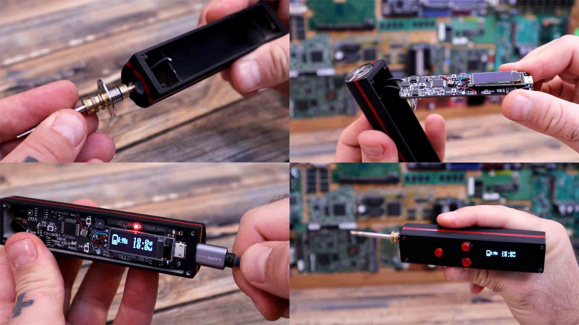
Is time to add the case. You have the design for download on the link below. I’ve printed the case with PLA material, 2 perimeters and 20% infill and without supports. The case is made in such a way that it will keep the battery pads in place. Once I’ve made sure the PCB fits inside together with the battery, I’ve sand paper it a little bit to be smoother and also painted it black with some spray paint. I also add some details with a different color to make it look better.
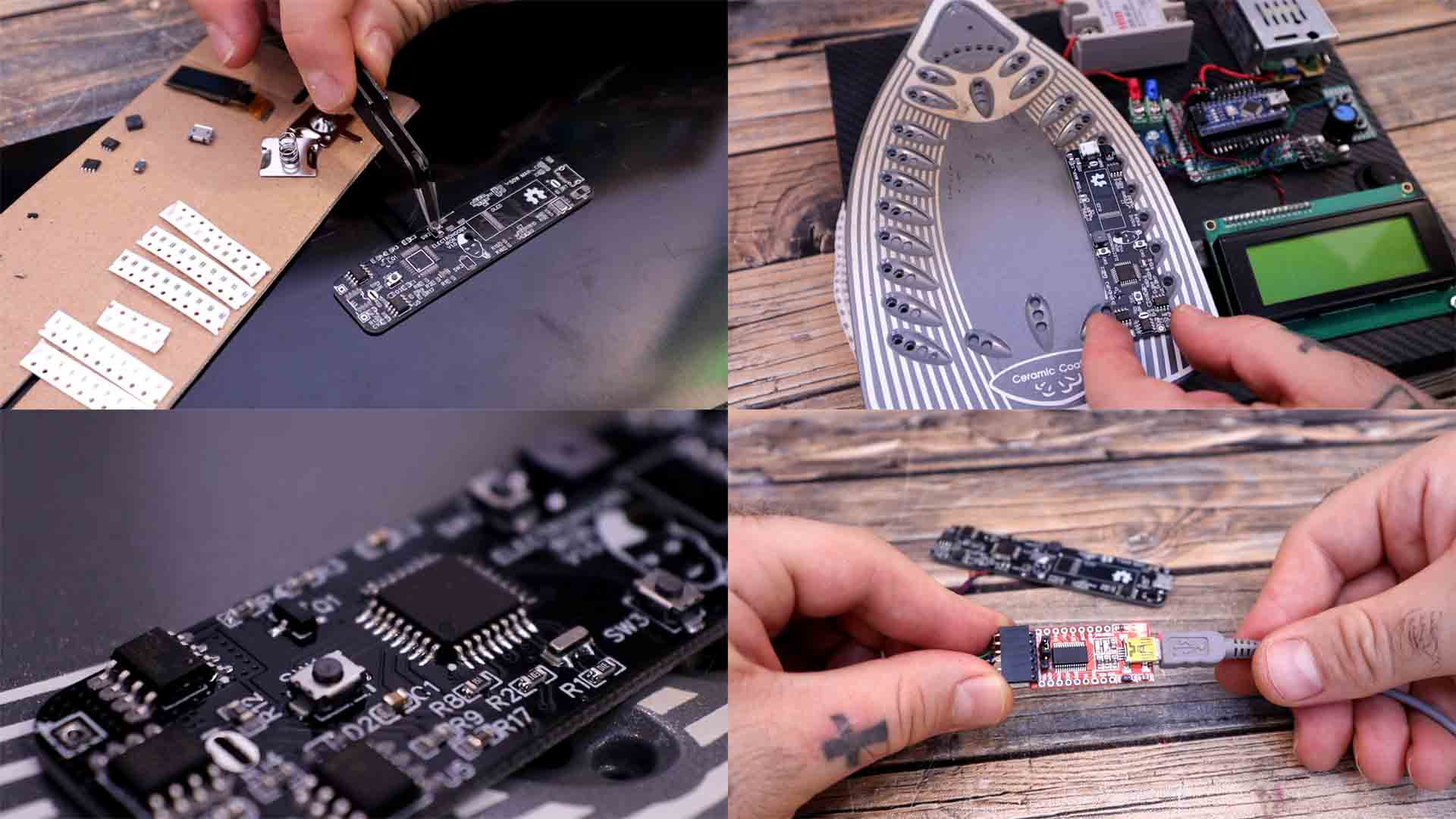
Let's solder the components. You can do this one by one, or do as I did, and use the SMD stencil, solder paste and reflow all the components at once using my homemade reflow hot plate. To make it fast and easier, I’ve took my ATMega238 microcontroller from an old Arduino NANO, in this way it already has a bootloader and I know that it works. Prepare all the components on the side before you apply the paste. Now I add some other PCBs around using scotch tape so my PCB will stay fixed in place. Then I put the SMD stencil on top to be aligned with the pads. I add some paste and using a spatula I fill all the holes. Now, all pads have some paste.

One by one, I now add all the components using some tweezers. This is a slow process but is faster than soldering the components one by one. All components are in place. I get my homemade reflow station and turn it on. I place the PCB on top and reflow the components. SHOW. And there you go. All components are soldered in their place. Once you have the PCB, connect an external FTDI programmer to the UART pads and upload a test code to make sure that it works. In my case I always upload a counter and open the serial monitor. If you get the numbers, then the microcontroller works.

Now we can upload the soldering iron code that you could find below on the next chapter if you want to use it. Compile and upload the code to the PCB. Now we pass the screw terminal though the hole and tight the nut on the other side. The case is made in such a way that it should fit perfectly. Now solder the wires back to the PCB and fix the board in place. Check if the USB connector could be inserted and charge the battery. If yes, we add these tiny buttons to the top case and close it. To close it we use some small screws and that’s it. My homemade portable and battery based soldering iron is complete.

Get the code from below and maybe consider supporting my work as well. You will aslo need the library for the OLED screen so download taht as well and go to sketch, include library adn add .zip library and there select the zip file you have just downloaded. Compile, connect the FTDI mdoule to the PCB and uplaod the code. Read the comments in the code for more.
//Inputs/Outputs
#define MOSFET 3
#define BUZZER 5
#define RES_DIVIDER 4
#define BAT_IN A0
#define ACS_IN A2
#define LM358_1 A1
#define LM358_2 A3
#define SW1 8
#define SW2 10
#define SW3 9
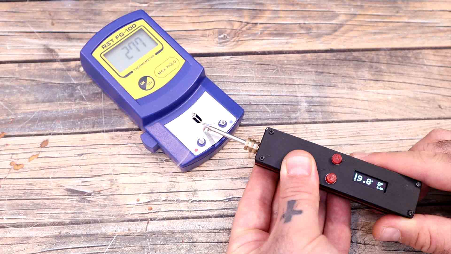
I get my thermocouple thermometer. I place the tip on top and press the button for 10 seconds. And look, it reached over 300 degrees in only 11 seconds. I think the power is enough and this tool should be more than useful when I work outside my workshop. In a different test, as you can see the tip was cold and I could touch it with my fingers. I press the button and as you can see in less than 8 seconds, we can melt solder. Pretty nice right?
The iron is small, very comfortable to use, it weighs just a few grams, is very easy to change the tip shape since we have all sort of tips on the market. The battery is rechargeable with a USB connector and 5V adaptor that we all have. The firmware is simple but could be improve a lot with multiple modes and more features. I’m studying a way of also measuring the temperature so stay tuned for more. I hope that you like this project and maybe make one yourself as well. If my videos help you, consider supporting my work on my PATREON or a donation on my PayPal. Thanks again and see you later guys.