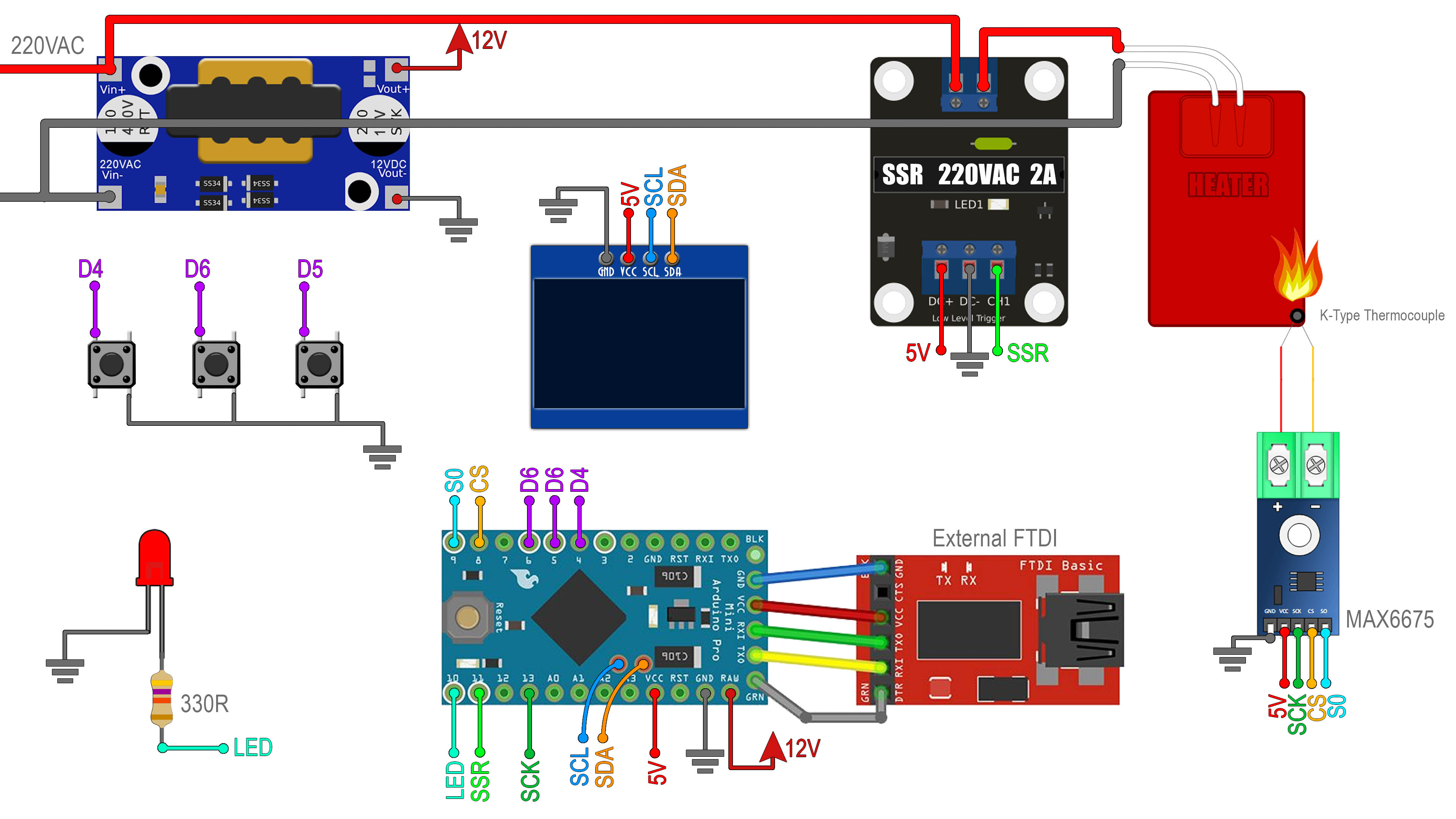
Below you have the full code for the controller. We have 3 main loops. When the heater is cold and we just turn it on we have the ramp up loop, where the SSR is fully turned on. When we get close to the desired value, we start some sort of PID control. That would change the pulses applied to the SSR. The frequency of these pulses must be low since the AC signal is only 50 or 60 hertz depending on your country. With some lines in the code I set that pulse to 30 hertz. When we power off the controller, we go to the cool down loop where we power off the relay but we are still monitoring the temperature. To detect the 3 push buttons, I’m using interruptions and a debounce in order to make sure we don’t read noise. Read the code line by line for more.
#include <EEPROM.h>               //Used to save setpoint when power-off

#include <SPI.h>
#include <Wire.h>
#include <Adafruit_GFX.h>         //download here: https://www.electronoobs.com/eng_arduino_Adafruit_GFX.php
#include <Adafruit_SSD1306.h>     //downlaod here: https://www.electronoobs.com/eng_arduino_Adafruit_SSD1306.php
#define OLED_RESET 5
Adafruit_SSD1306 display(OLED_RESET);


#include "max6675.h"              //download here: https://electronoobs.com/eng_arduino_max6675.php
int thermoDO = 9;
int thermoCS = 8;
int thermoCLK = 13;
MAX6675 thermocouple(thermoCLK, thermoCS, thermoDO);

//Arduino Pins
#define SSR_PIN  11
#define but_up  4
#define but_down  5
#define but_stop  6
#define led  10

//Variables
uint8_t state = 0;
bool D4_state = 1;
bool D5_state = 1;
bool D6_state = 1;
bool LED_State = LOW;
float prev_isr_timeD4, prev_isr_timeD5, prev_isr_timeD6;

float real_temp;           //We will store here the real temp
float Setpoint = 100;      //In degrees C
float SetpointDiff = 30;   //In degrees C
float elapsedTime, now_time, prev_time;        //Variables for time control
float refresh_rate = 200;                   //PID loop time in ms
float now_pid_error, prev_pid_error;


///////////////////PID constants///////////////////////
float kp=2.5;         //Mine was 2.5
float ki=0.06;         //Mine was 0.06
float kd=0.8;         //Mine was 0.8
float PID_p, PID_i, PID_d, PID_total;
///////////////////////////////////////////////////////


void setup() {
  cli();
  Setpoint = EEPROM.read(0)+1; //we adf
  sei();

  Serial.begin(250000);     //For debug
  pinMode(SSR_PIN, OUTPUT);
  digitalWrite(SSR_PIN, HIGH);    // When HIGH, the SSR is Off

  pinMode(led, OUTPUT);
  digitalWrite(led, LOW);
  real_temp = thermocouple.readCelsius();

  TCCR2B = TCCR2B & B11111000 | B00000111;    // D11 PWM is now 30.64 Hz

  pinMode(but_up, INPUT_PULLUP);
  pinMode(but_down, INPUT_PULLUP);
  pinMode(but_stop, INPUT_PULLUP);
  PCICR |= B00000100;      //Bit2 = 1 -> "PCIE2" enabeled (PCINT16 to PCINT23)
  PCMSK2 |= B01110000;     //PCINT20, CINT21, CINT22 enabeled -> D4, D5, D6 will trigger interrupt

  display.begin(SSD1306_SWITCHCAPVCC, 0x3C);  // initialize with the I2C addr 0x3C (for the 128x32 or 64 from eBay)
  delay(100);
  display.clearDisplay();
  display.setTextSize(2);
  display.setTextColor(WHITE,BLACK);
  display.display();
  delay(100);
  //EEPROM.write(1, Setpoint);

}

void loop() {
  if(state == 0){
    ramp_up();
  }
  else if (state == 1){
    PID_control();
  }
  else{
    cool_down();
  }
}


//Fucntion for ramping up the temperature
void ramp_up(void){
  //Rising temperature to (Setpoint - SetpointDiff)
  elapsedTime = millis() - prev_time;
  if(elapsedTime > refresh_rate){
    real_temp = thermocouple.readCelsius();

    if(real_temp < (Setpoint - SetpointDiff)){
      digitalWrite(SSR_PIN, LOW);                //Turn On SSR
      digitalWrite(led, HIGH);
    }
    else
    {
      digitalWrite(SSR_PIN, HIGH);                 //Turn Off SSR
      digitalWrite(led, LOW);
      state = 1;                                  //Already hot so we go to PID control
    }

    display.clearDisplay();
    display.setCursor(0,0);
    display.print("Set: ");
    display.println(Setpoint,1);

    display.print((char)247);
    display.print("C: ");
    display.println(real_temp,1);
    display.print("Ramp Up");
    display.display();//Finally display the created image
    Serial.println(real_temp);                //For debug only
    prev_time = millis();
  }
}//End of ramp_up loop


//Main PID compute and execute function
void PID_control(void){
  elapsedTime = millis() - prev_time;
  if(elapsedTime > refresh_rate){
    //1. We get the temperature and calculate the error
    real_temp = thermocouple.readCelsius();
    now_pid_error = Setpoint - real_temp;

    //2. We calculate PID values
    PID_p = kp * now_pid_error;
    PID_d = kd*((now_pid_error - prev_pid_error)/refresh_rate);
    //2.2 Decide if we apply I or not. Only when error is very small
    if(-3 < now_pid_error && now_pid_error < 3){
      PID_i = PID_i + (ki * now_pid_error);}
    else{PID_i = 0;}

    //3. Calculate and map total PID value
    PID_total = PID_p + PID_i + PID_d;
    PID_total = map(PID_total, 0, 150, 0, 255);

    //4. Set limits for PID values
    if(PID_total < 0){PID_total = 0;}
    if(PID_total > 255) {PID_total = 255; }

    //5. Write PWM signal to the SSR
    analogWrite(SSR_PIN, 255-PID_total);

    //6. Print values to the OLED dsiplay
    display.clearDisplay();

    display.setCursor(0,0);
    display.print("Set: ");
    display.println(Setpoint,1);

    display.print((char)247);
    display.print("C: ");
    display.println(real_temp,1);
    display.println("PID mode");
    display.print(PID_total);
    display.display();//Finally display the created image


    //7. Save values for next loop
    prev_time = millis();                       //Store time for next loop
    prev_pid_error = now_pid_error;             //Store error for next loop
    //Serial.println(elapsedTime);                //For debug only
    LED_State = !LED_State;
    digitalWrite(led, LED_State);
  }
}//End PID_control loop


//Function for turning off everything and monitoring the coolidn down process
void cool_down(void){
  digitalWrite(SSR_PIN, HIGH);    //SSR is OFF with HIGH pulse!
  digitalWrite(led, LOW);
  elapsedTime = millis() - prev_time;
  if(elapsedTime > refresh_rate){
    display.clearDisplay();

    display.setCursor(0,0);
    display.print("Set: ");
    display.println(Setpoint,1);

    display.print("Off");
    display.display();//Finally display the created image
    prev_time = millis();
  }
}//End cool_down loop


ISR (PCINT2_vect)
{
  cli();
  //1. Check D4 pin HIGH
  if(PIND & B00010000){
    if(D4_state == 0){
      D4_state = 1;
      prev_isr_timeD4 = millis();
    }

  }
  else if (D4_state == 1 && (millis() - prev_isr_timeD4 > 2)){
    Setpoint ++;
    int st = Setpoint;
    EEPROM.write(0, st);
    D4_state = 0;
  }


  //2. Check D5 pin HIGH
  if(PIND & B00100000){
    if(D5_state == 0){
      D5_state = 1;
      prev_isr_timeD5 = millis();
    }

  }
  else if (D5_state == 1 && (millis() - prev_isr_timeD5 > 2)){
    Setpoint --;
    int st = Setpoint;
    EEPROM.write(0, st);
    D5_state = 0;
  }


  //3. Check D6 pin HIGH
  if(PIND & B01000000){
    if(D6_state == 0){
      D6_state = 1;
      prev_isr_timeD6 = millis();
    }

  }
  else if (D6_state == 1 && (millis() - prev_isr_timeD6 > 2)){
    if(state == 0 || state == 1){
      state = 2;
    }
    else if (state == 2){
      state = 0;
    }
    D6_state = 0;
  }
  sei();


}