The idea behind this tutorial is to make somethiong like this module here that you could buy from eBay, but make the homemade version. This is a radio controlled relay module. This tutorial will show you how to make the remote controller and the receiver with the relay. The receiver will be powered directly from 220VAC so it will work independent from the transmitter and will not need batteries. The radio transmitter will work with a 3.7V battery. I will show you how to implement the ultra-low power mode on the Arduino so it could last a few years with one charge. With multiple buttons you could control multiple relays around the house for light bulbs, fans, TVs, etc...
Below you have all the parts needed for radio relay control project for both receiver and transmitter. I've selected components that could be small enough to fit isnide a commercial 220V outlet. For the case, you can select any other option, maybe even directly isnide the wall connected to the 220V wires of the oulet, light or any other wires. Check the list below and make the PCB.
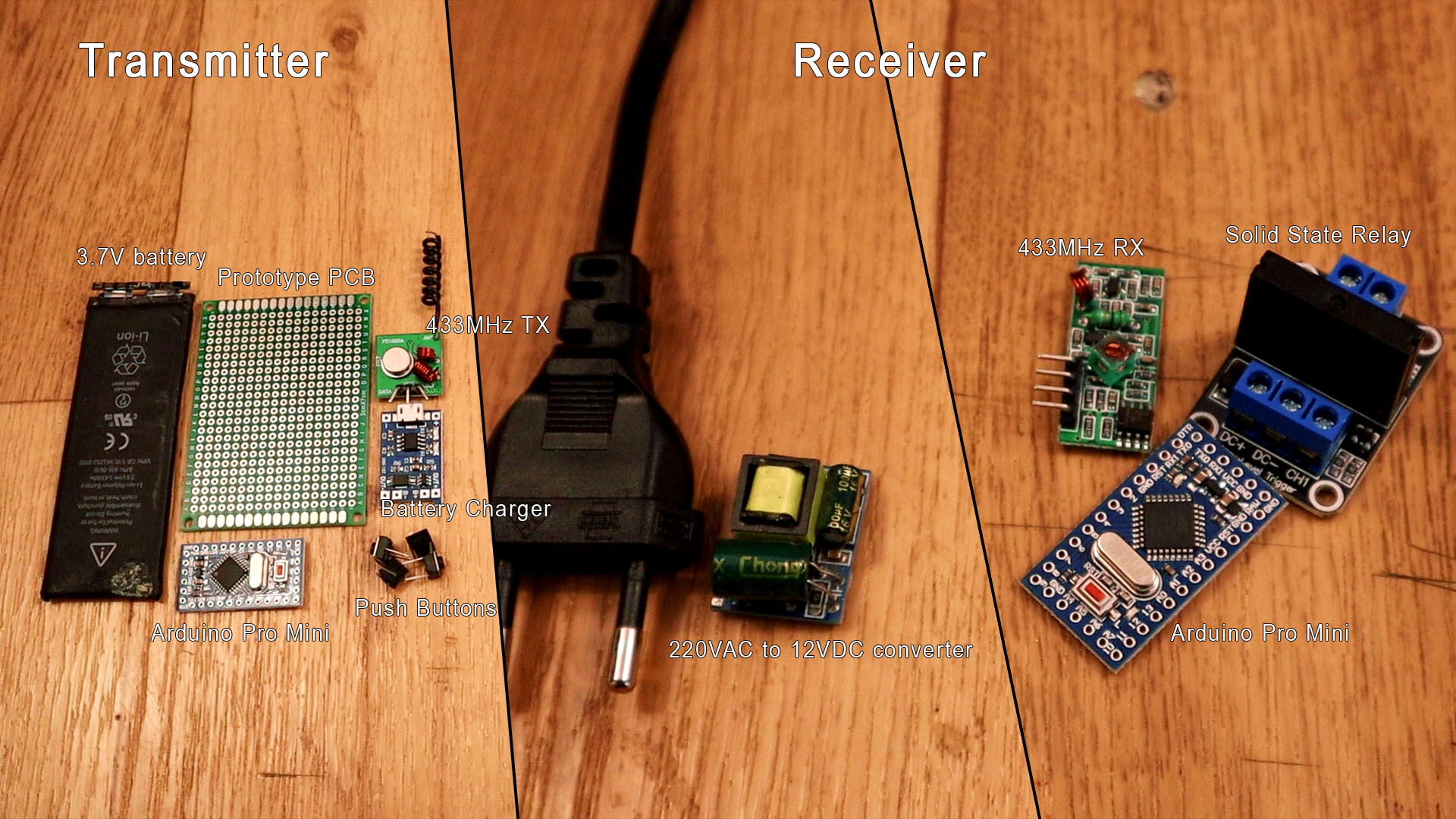
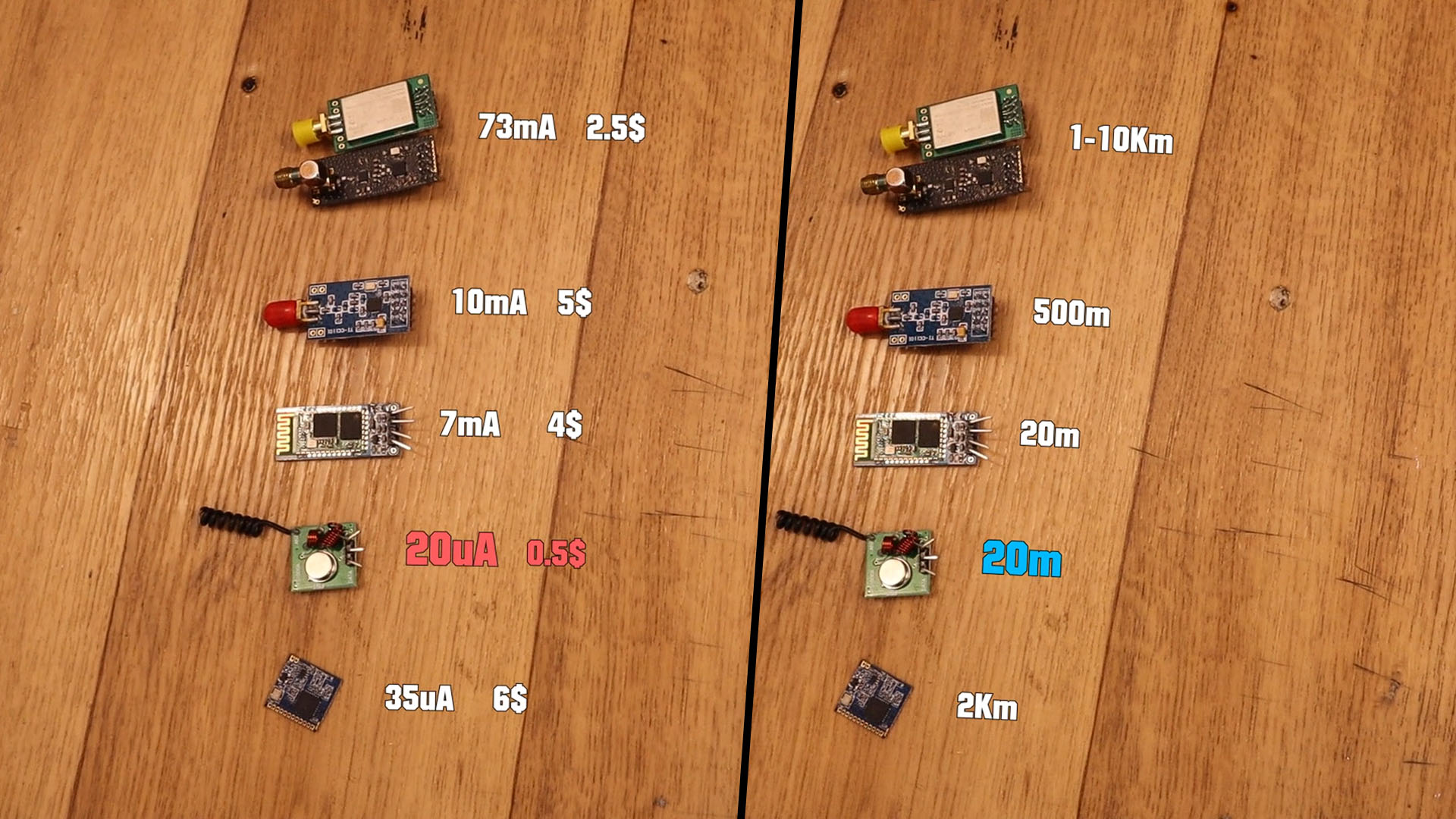
The radio transmitter remote must be low power. Why? Well because you don't want to charge the remote to control your home lights each week. Usually these remoret last for years with one set of batteries. For that we need to make the Arduino be low-power and also select the radio module with the lowest power consumption. In my case I've tested all transmitter modules below and the 433MHz pair mdoules were the ones that least power consumption have at the voltage of the battery. Now these are the onew with the lowest range, around 20m. But for this project we don't need more than that since we want to control relays around the same room. Also, these modules are the cheapest ones. That's why I've selected the 433MHz radios.
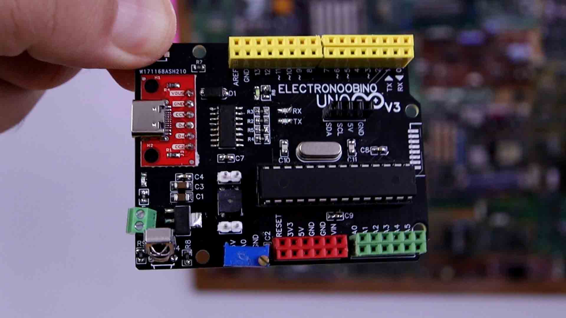
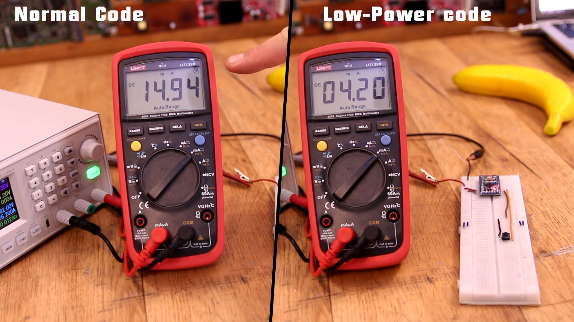
We now have a low power radio module. But the Arduino Pro Mini by itself when running will draw as you can see below, around 15mA of current. So suposing a 500mAh battery, hat would last 30 hopurs or so, so a little bit more tahn a day. We want way more than that, so we need to lower the power consumprion. One thing we can do, is to implement the low power mode on the Arduino Pro Mini. With the low power code, as you can see below, the Arduino will draw only 4.2mA which is still too much. We will lower the consumption even more by removing parts. But first, see the low power code below.
See the code below that will implement low-power mode. Read each line. The idea is that using tgis line set_sleep_mode(SLEEP_MODE_PWR_DOWN); we can eneble the ultra low power mode.
#include <avr/interrupt.h>      // library for interrupts handling
#include <avr/sleep.h>          // library for sleep
#include <avr/power.h>          // library for power control

void setup() {
  PCICR |= B00000100;   //Port D intrruptions enabled
  PCMSK2 |= B00000100;  //PCINT18 -> Pin D2 will trigger interruption
  delay(100);
  //We activate LOW power mode
  set_sleep_mode(SLEEP_MODE_PWR_DOWN);
  cli();
  sleep_bod_disable();
  sei();
  sleep_cpu();
  sleep_enable();
}

//Void loop won't run only if sleep mode is disabled.
void loop() {
  delay(3000); //Delay to simulate the radio data send code...

  //We activate back LOW power mode and wait for next interruption
  set_sleep_mode(SLEEP_MODE_PWR_DOWN);
  cli();
  sleep_bod_disable();
  sei();
  sleep_cpu();
  sleep_enable();
}

//Each time we push the button on D2, the ISR will trigger and disable sleep mode
ISR(PCINT2_vect)
{
  sleep_disable();
}
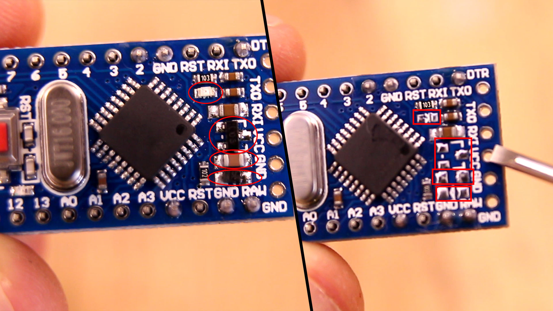
We don't need the power ON LED so we could remove that. The Arduino will be powered directly from the 3.7V battery connected to Vcc so, won't need the 5V voltage regulator neighter so we could remove the input diode, the regulator and the decupling input capacitor as well. That will lower the power consumption a lot. As you can see below, we now use only 90uA which is a very low value. With a 500mAh battery taht will last 5600 hours or 231 days which is a lot better!
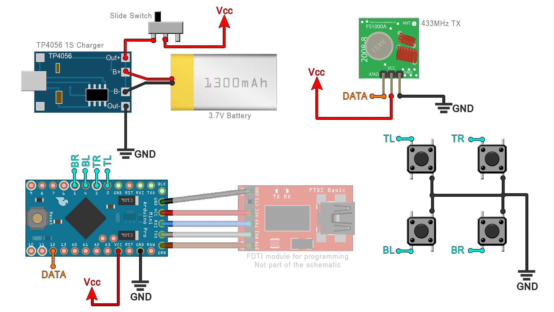
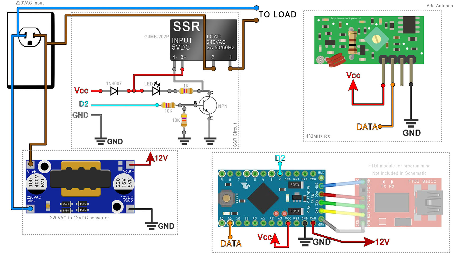
Below you have the scheamtic for the transmitter. We connect the battery to the charger and we add a slide switch at the output in order to be able to totally turn off the remote. We supply Vcc to the Arduino and transmitter. The FTDI module is not part of the scheamtic, is just used to upload the code once. Connect all 4 buttons to GND on one side, and the other side connect it to pins D2 to D5. The DATA pin for the radio module goes to D12 pin for the SPI connection.
This is the transmitter code for the 433MHz radio controller and relay control. Make the connections as below and use SPI pin D12 for the transmitter radio module. You will also need to download and install the RadioHead library from below. We use that library with the 433MHz modules. This code also includes the low-power mode and interruptions for D2 to D5 pins. Curerent draw 90uA.
#include <avr/interrupt.h>      // library for interrupts handling
#include <avr/sleep.h>          // library for sleep
#include <avr/power.h>          // library for power control
#include <RH_ASK.h>
#include <SPI.h>                // Not actually used but needed to compile
RH_ASK driver;                  // Create the TX instance
Below you have the scheamtic for the receiver. Since the solid state relay module on the PCB is too big, I had to take it out from the PCB and solder the circuit on a small PCB so it could fit inside the case. You have the circuit below with a NPN transistor and a few resistors. Connect 220VAC to the converter and the 12VDC output connect it to the RAW pin of the Arduino Pro Mini. Connect pin D2 to the relay circuit. Connect D11 to the radio receiver. Share GND with the entire ciruit.
This is the receiver code for the 433MHz radio controller and relay control. Make the connections as below and use SPI pin D11 for the receiver radio module. You will also need to download and install the RadioHead library from below. We use that library with the 433MHz modules.
//Outputs
int Pin_D2 = 2;       //Connect to relay1 pin
int Pin_D3 = 3;       //Connect to relay2 pin
int Pin_D4 = 4;       //Connect to relay3 pin
int Pin_D5 = 5;       //Connect to relay4 pin
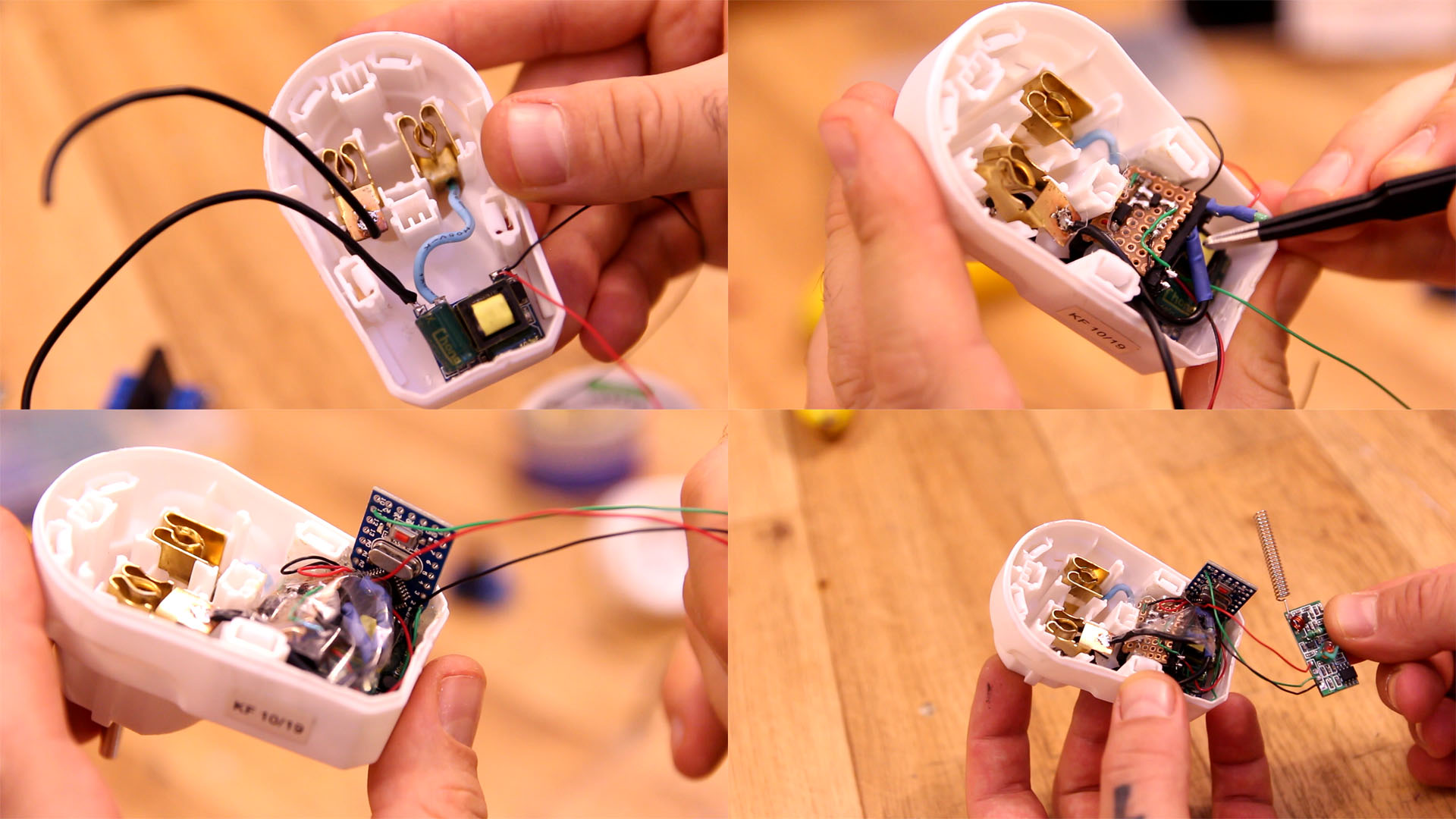
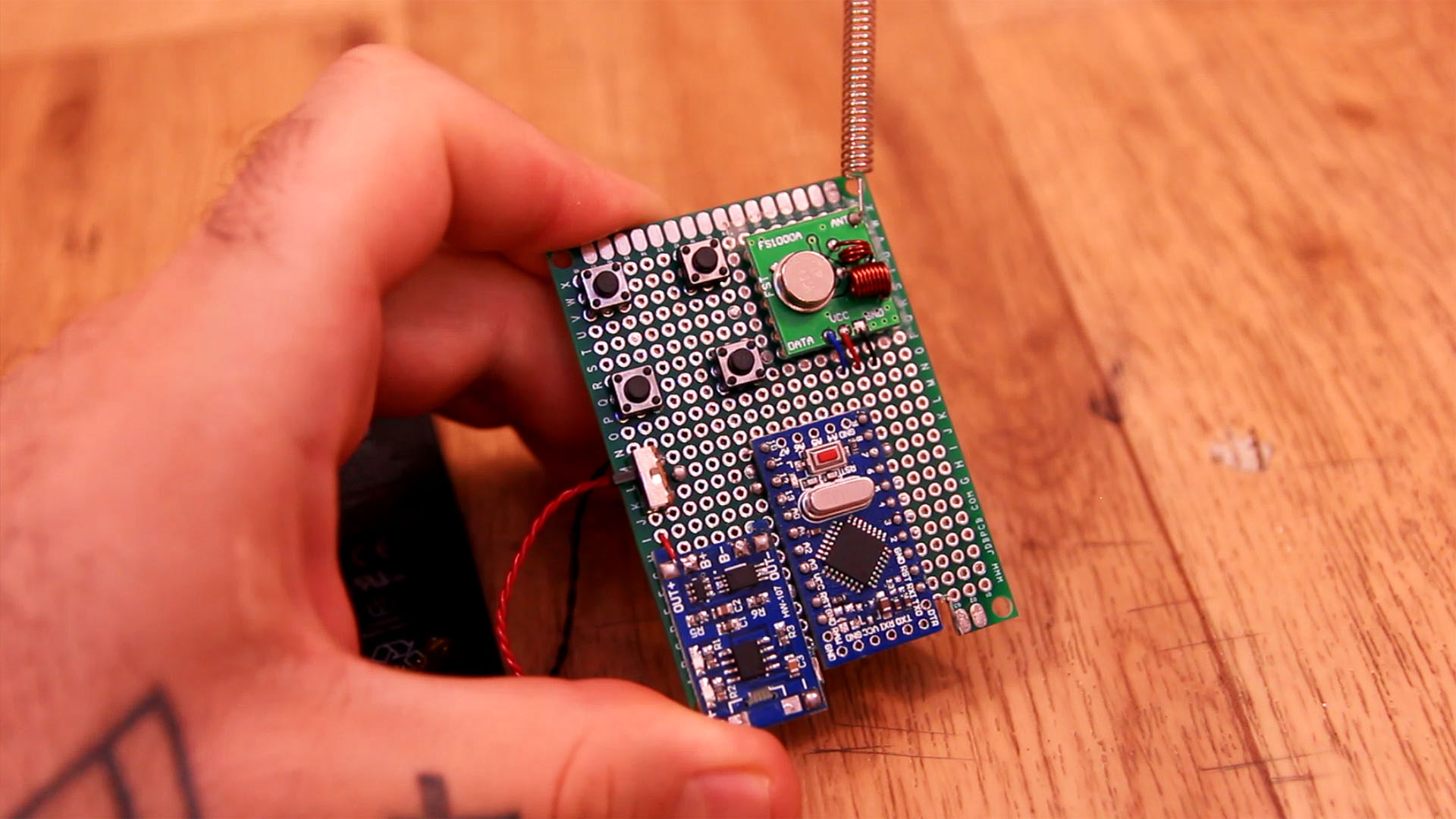
So, get the transmitter schematic and mount it on the prototype PCB. Solder all the modules and then use thin wires to make the connections. Upload the TX code to the Arduino and that's it.
Before we mount everything inside the case, as you cansee the SSR module is too big. So take it out and solder the circuit from the receiver scheamtic on a tiny PCB. Then I glue that PCB on top of the relay. As you can see below, now the SSR ia a lot smaller so it will fit better. To make the circuit I've used the same components from the original PCB, just desolder and use them again.
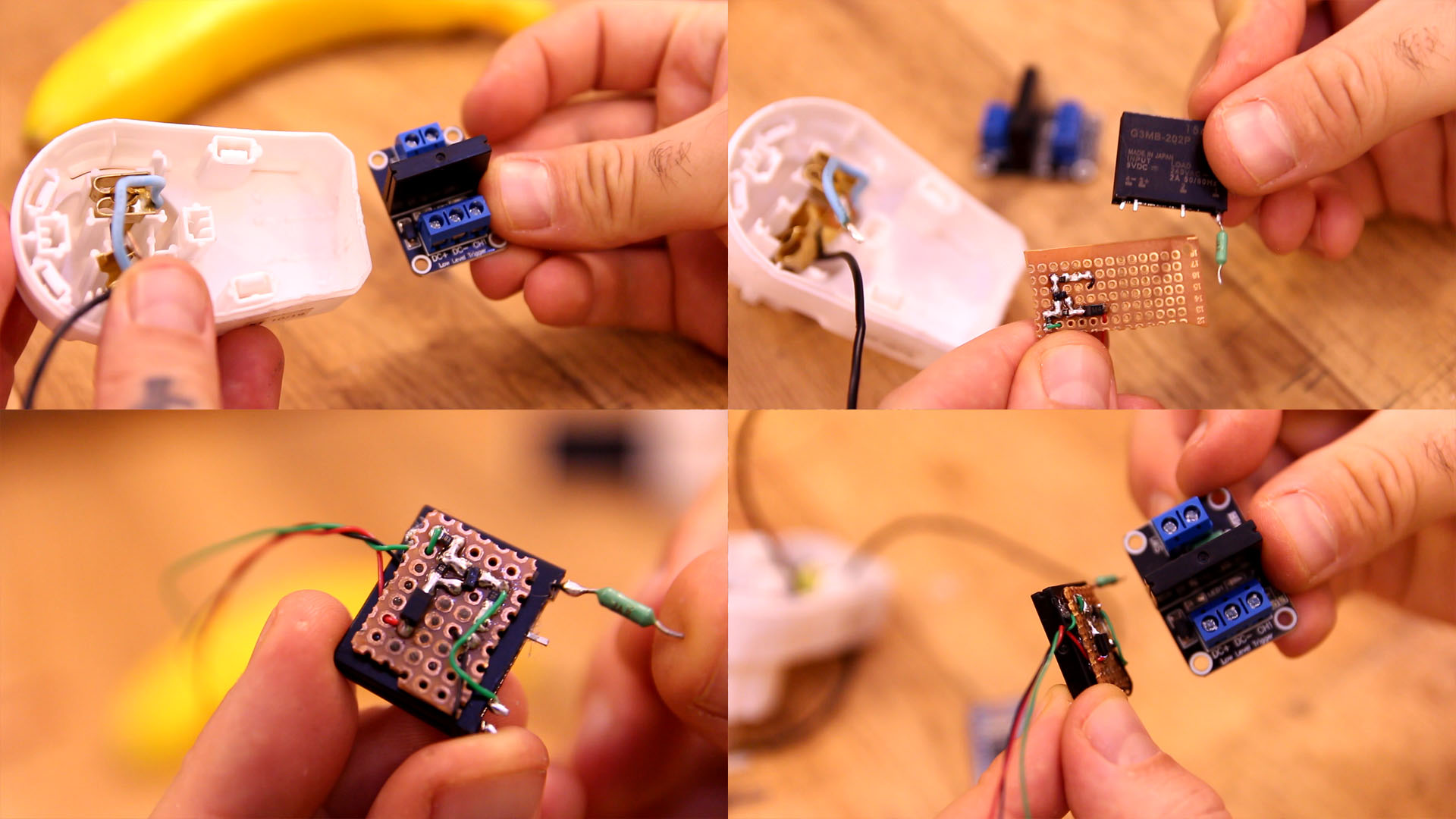
Ok, get the case and remove the switch so we have more space. First solder the 220VAC to 12VDC converter. Add thin wires at the 12V output taht we will later connect to the Arduino. Next, on top add the relay and solder one phase to the 220VAC input. The other phase is connected direectly to the LOAD.