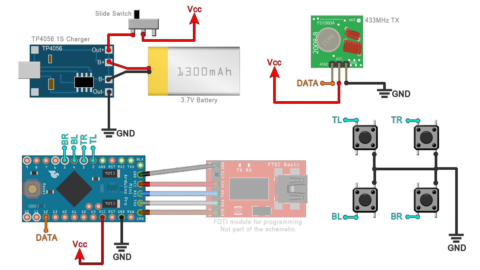
This is the transmitter code for the 433MHz radio controller and relay control. Make the connections as below and use SPI pin D12 for the radio module. You will also need to download and install the RadioHead library from below. We use that library with the 433MHz modules. This code also includes the low-power mode and interruptions for D2 to D5 pins. Curerent draw 90uA. Download the code from below or copy+paste.
#include <avr/interrupt.h>      // library for interrupts handling
#include <avr/sleep.h>          // library for sleep
#include <avr/power.h>          // library for power control

#include <RH_ASK.h>             //Download it here https://electronoobs.com/eng_arduino_RadioHead.php
#include <SPI.h>                // Not actually used but needed to compile
RH_ASK driver;                  // Create the TX instance


//Inputs
int TR = 2;                     //Button TL
int TL = 3;                     //Button TR
int BR = 4;                     //Button BL
int BL = 5;                     //Button BR
//Initial state of the buttons
bool TR_state = true;           //Set to true because it has pullup
bool TL_state = true;           //Set to true because it has pullup
bool BR_state = true;           //Set to true because it has pullup
bool BL_state = true;           //Set to true because it has pullup

//State of the button (pushed or not)
bool TR_pushed = false;
bool TL_pushed = false;
bool BR_pushed = false;
bool BL_pushed = false;

int delay_time = 300;               //Delay time after turnning output On/Off
long debouncing_time = 15;          //Debouncing Time in Milliseconds
volatile unsigned long last_micros;

void setup()
{
  PCICR |= B00000100;           //Port D intrruption -> PCINT 16-23 (D0-D7)
  PCMSK2 |= B00000100;          //PCINT18 -> Pin D2 is set to trigger interruption
  PCMSK2 |= B00001000;          //PCINT19 -> Pin D3 is set to trigger interruption
  PCMSK2 |= B00010000;          //PCINT20 -> Pin D4 is set to trigger interruption
  PCMSK2 |= B00100000;          //PCINT21 -> Pin D5 is set to trigger interruption

  pinMode(TR, INPUT_PULLUP);    //Set the button inputs with pullup to Vcc
  pinMode(TL, INPUT_PULLUP);    //Set the button inputs with pullup to Vcc
  pinMode(BR, INPUT_PULLUP);    //Set the button inputs with pullup to Vcc
  pinMode(BL, INPUT_PULLUP);    //Set the button inputs with pullup to Vcc

  Serial.begin(9600);    // Debugging only
  if (!driver.init()){
    Serial.println("init failed");
  }
  put_to_sleep();               //Run the code to put Arduino to low power
}

/////////////////////////////////////////////////////////////////////////////////////////////

//This is the fucntion taht puts the Arduino to low power mode
void put_to_sleep(){
  //We activate LOW power mode
  set_sleep_mode(SLEEP_MODE_PWR_DOWN);
  cli();
  sleep_bod_disable();
  sei();
  sleep_cpu();
  sleep_enable();
}

/////////////////////////////////////////////////////////////////////////////////////////////

void loop()
{
    if(TR_pushed){                                  //If TOP RIGHT button was pusshed
      TR_pushed = false;
      const char *msg = "2";
      driver.send((uint8_t *)msg, strlen(msg));
      driver.waitPacketSent();
      delay(delay_time);
      put_to_sleep();                               //Put the Arduino back to sleep mode
    }

    if(TL_pushed){                                  //If TOP LEFT button was pusshed
      TL_pushed = false;
      const char *msg = "3";
      driver.send((uint8_t *)msg, strlen(msg));
      driver.waitPacketSent();
      delay(delay_time);
      put_to_sleep();                               //Put the Arduino back to sleep mode
    }

    if(BR_pushed){                                  //If BOTTOM RIGHT button was pusshed
      BR_pushed = false;
      const char *msg = "4";
      driver.send((uint8_t *)msg, strlen(msg));
      driver.waitPacketSent();
      delay(delay_time);
      put_to_sleep();                               //Put the Arduino back to sleep mode
    }

    if(BL_pushed){                                  //If BOTTOM LEFT button was pusshed
      BL_pushed = false;
      const char *msg = "5";
      driver.send((uint8_t *)msg, strlen(msg));
      driver.waitPacketSent();
      delay(delay_time);
      put_to_sleep();                               //Put the Arduino back to sleep mode
    }
}//End Void Loop


/////////////////////////////////////////////////////////////////////////////////////////////

/*This is the interruption vector. Pins D2 to D5 are confugured o trigger an interruption each
time they cahnge their value (Low or High). That will run this loop and as you can see, first we
tahe the Arduino out of sleep mode. We detect which button was pressed and we change the "_pushed"
variable that we later use in the "void loop" and send radio data numbers from 2 to 5*/
ISR(PCINT2_vect)
{
  sleep_disable();    //Stop low power mode
  cli();              //Stop interrupts for a while
  if((long)(micros() - last_micros) >= debouncing_time * 1000) {
    ////////////////////////////////////////////////////
    if(PIND & B00000100){           //D2 was released
      if(TR_state == false){
        TR_state = true;
      }
    }
    else if(TR_state == true){      //D2 was pushed
      TR_state = false;
      if(TR_pushed == false){
        TR_pushed =  true;
      }
    }
    /////////////////////////////////////////////////////


    ////////////////////////////////////////////////////
    if(PIND & B00001000){           //D3 was released
      if(TL_state == false){
        TL_state = true;
      }
    }
    else if(TL_state == true){      //D3 was pushed
      TL_state = false;
      if(TL_pushed == false){
        TL_pushed =  true;
      }
    }
    /////////////////////////////////////////////////////


    ////////////////////////////////////////////////////
    if(PIND & B00010000){           //D4 was released
      if(BR_state == false){
        BR_state = true;
      }
    }
    else if(BR_state == true){      //D4 was pushed
      BR_state = false;
      if(BR_pushed == false){
        BR_pushed =  true;
      }
    }
    /////////////////////////////////////////////////////

    ////////////////////////////////////////////////////
    if(PIND & B00100000){           //D5 was released
      if(BL_state == false){
        BL_state = true;
      }
    }
    else if(BL_state == true){      //D5 was pushed
      BL_state = false;
      if(BL_pushed == false){
        BL_pushed =  true;
      }
    }
    /////////////////////////////////////////////////////
    last_micros = micros();
  }
}//End of ISR of port D