In this tutorial I will try to make the simplest analog video transmitter and send that signal over the radio frequencies and make our homemade "spy camera". The circuit is easy to make and requires just a few components. I’ll do my best to explain you how analog video signal works, more or less, and since I still have my analog black and white TV from the vintage teardown video, let’s see if I’ll be able to receive the video signal and display that on the analog TV. So guys, let’s get started.
As you can see, we need some resistors, capacitors, a coil, a small NPN transistor, a potentiometer, a diode and a wire for the antenna. Instead of the LC tank to create the carrier frequency, some circuits are using a crystal oscillator with a specific frequency. You could also try that if you want. To make the coil I get some copper wire and make 3 loops and 8mm diameter and 22 SWG wire. Peal the enamel from the tips and add some solder. You also need an analog video camera like the one below. These cameras work at 12V but be careful, sometimes they require only 5V or below that value. I guess these ones have a voltage regulator of some sort, but that’s good for us because in that way we can supply both the camera and the transmitter with the same voltage, let’s say 12V.
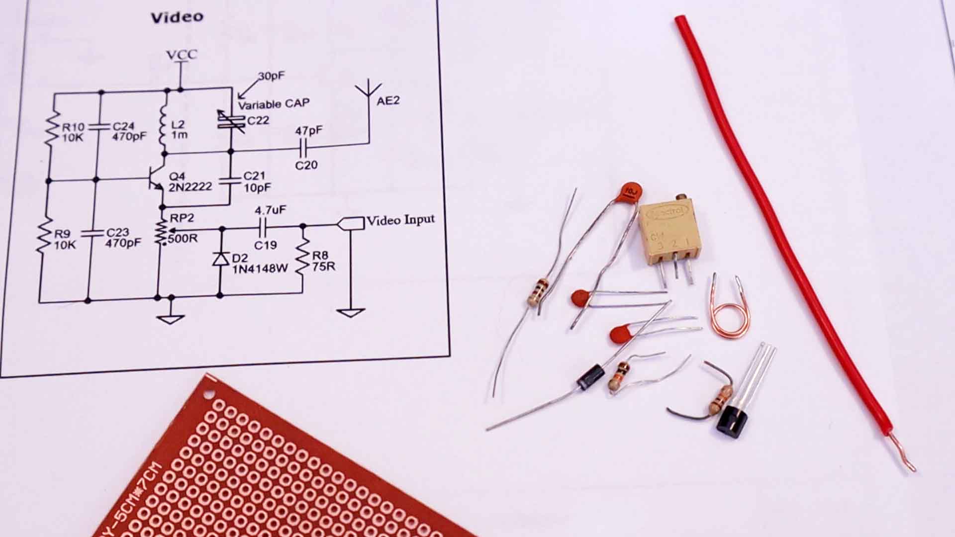
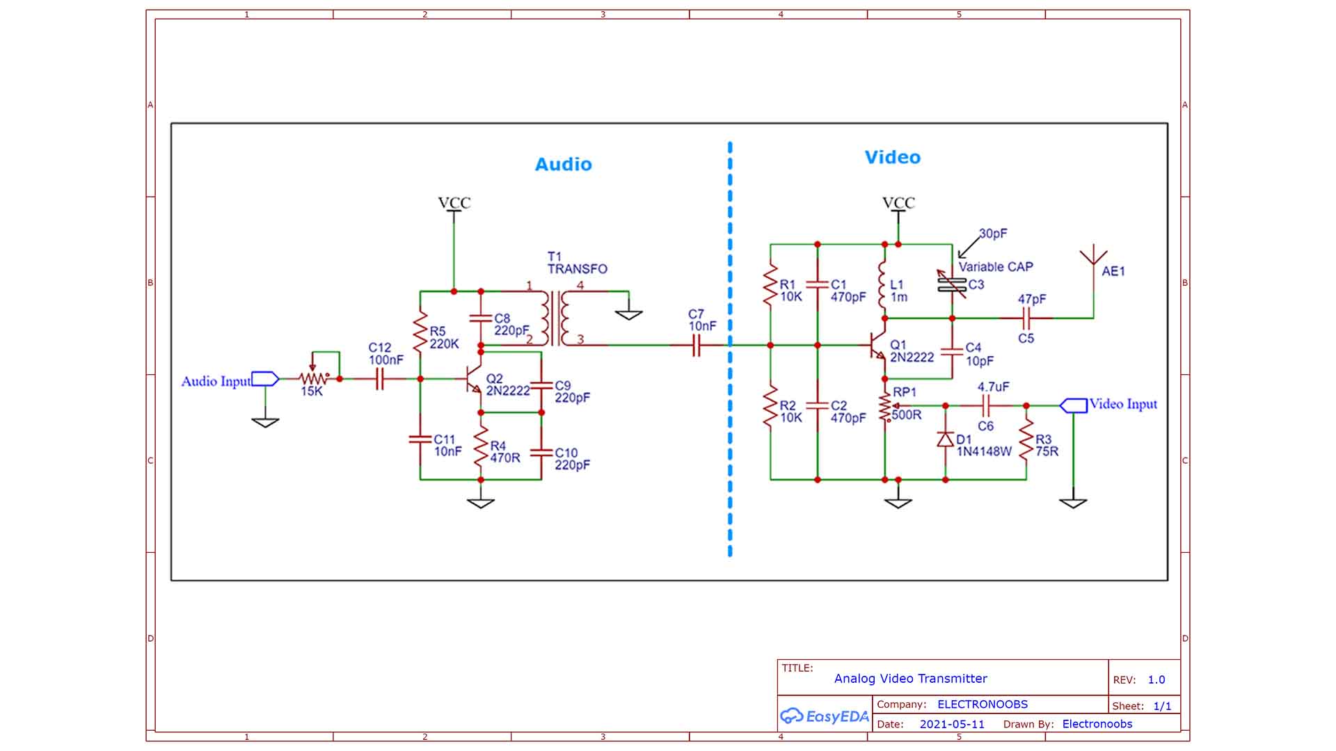
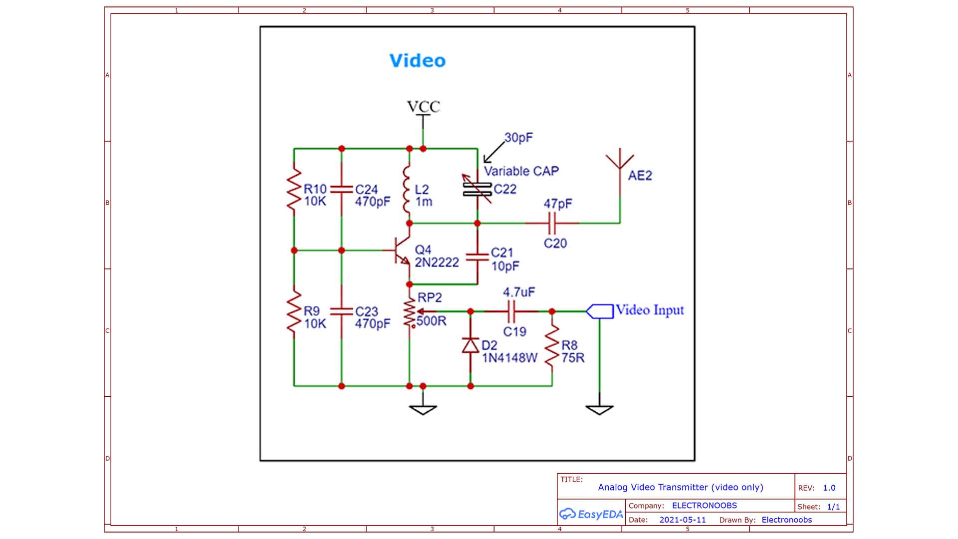
Now we need to send the video signal and for that I will use one of the schematics below which is very common on the internet, just google analog video transmitter and you will get a lot of circuits like this. Since we are only sending video, we can get rid of the audio part but if you also want to send audio, you can use the full schematic.
So in case you only want to send video, use the schematic below. From the camera, red wire is VCC, black is ground and the yellow is the video signal. If the camera also has a white cable, that’s means it also has a microphone and audio output. But for my example, I've only used video signal with the schematic below.
The coil and the capacitor is creating a so called LC tank. This, as we have seen in so many previous tutorials, will resonate at a specific frequency. That frequency will be our carrier and it must be high frequency since the very high band of the analog TV works between 174MHz and 216 Mhz. Then we take the video signal and we make the convolution with this carrier, so now the high frequency signal will carry our video signal and since we have the antenna connected, this will create an electro-magnetic wave which are basically radio waves and now the TV can read that signal and make the demodulation process and show the pictures on the screen. If you want to know how this analog TV works, watch my previous vintage teardown video.
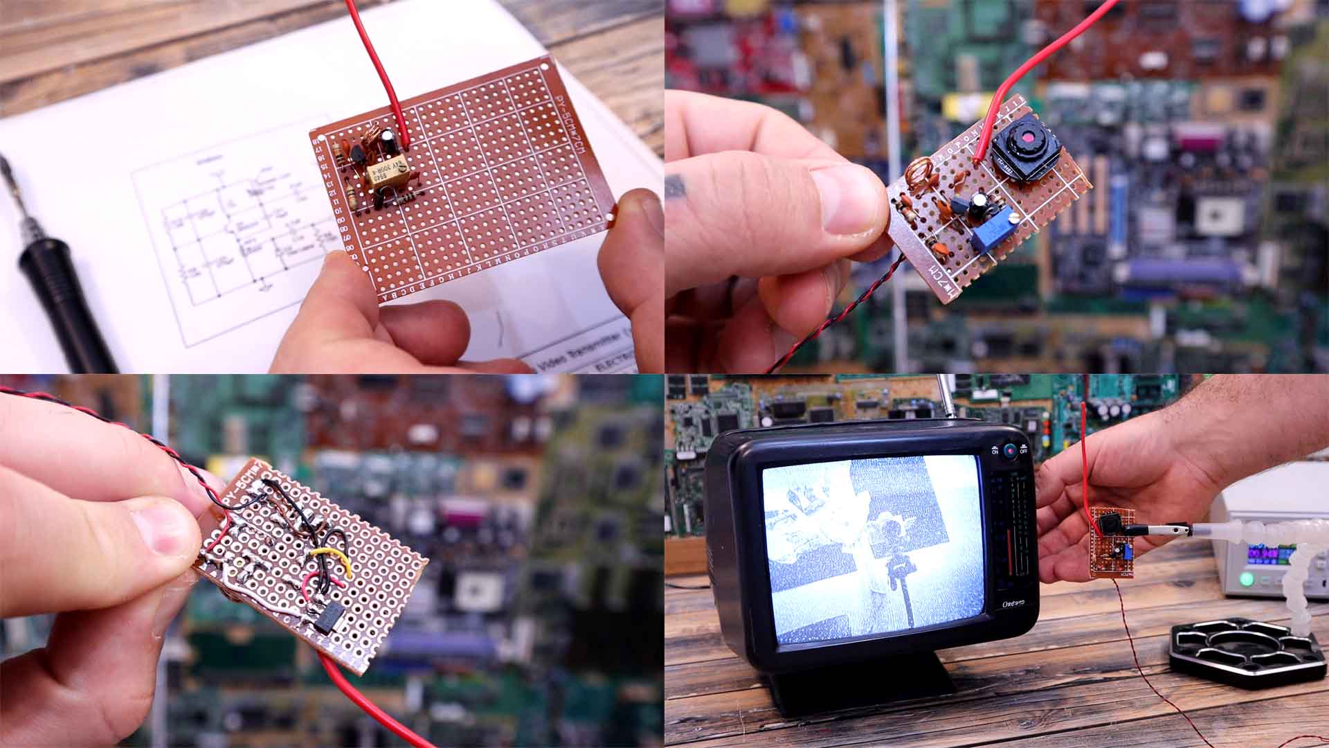
I first mounted the circuit on the breadboard and instead of a 30pF capacitor I’ve used a variable capacitor. So, in that way I was able to test the circuit for best results and then measured the capacitor and it was 30pF so I’ve used that value for the final circuit.
I solder the components. I solder the voltage divider and then the two capacitors. Then I solder the coil with the capacitor for the LC tank and also the BJT transistor and the rest of the components. I have the PCB and I cut it to size and also find a place for the camera as well and solder the wires to VCC and the video input. For the antenna I’ve just used a copper wire. Now we can supply this to a 12V battery and test it out. Start the TV and put it in VHF range of frequencies. I start rotating the knob and after a few seconds of tunning, there we have it. I receive the video from the small transmitter. Isn’t this amazing?
The circuit is simple but this technology is still amazing knowing is so old. Now you might need to tune a bit the circuit with the potentiometer or with a variable capacitor. Also, if the frames are moving up and down, usually, the TVs have a synchronizing dial so rotate that till you get steady frames.
So guys, that’s how analog video works, more or less, and that’s how you can make a video transmitter. Check all the schematics above and also the different cameras I had in this video and start testing around different configurations. You can find small analog TV receivers for very cheap and with that create your own FPV system. I don’t know for sure the range of this circuit, but maybe you could mount it, test it and share your results.
I hope you like this tutorial and maybe you have learned something new. If my videos help you, consider supporting my work on my PATREON or a donation on my PayPal. Thanks again and see you later guys.