In this tutorial I'll show you how the fluorescent tube creates light with electrodes creating electrons, mercury vapor and phosphor inside the tube. Then we analyse how the high voltage is created with the starter and ballast and then how the current flow is keept throgh the tube. I hope you will learn something new.
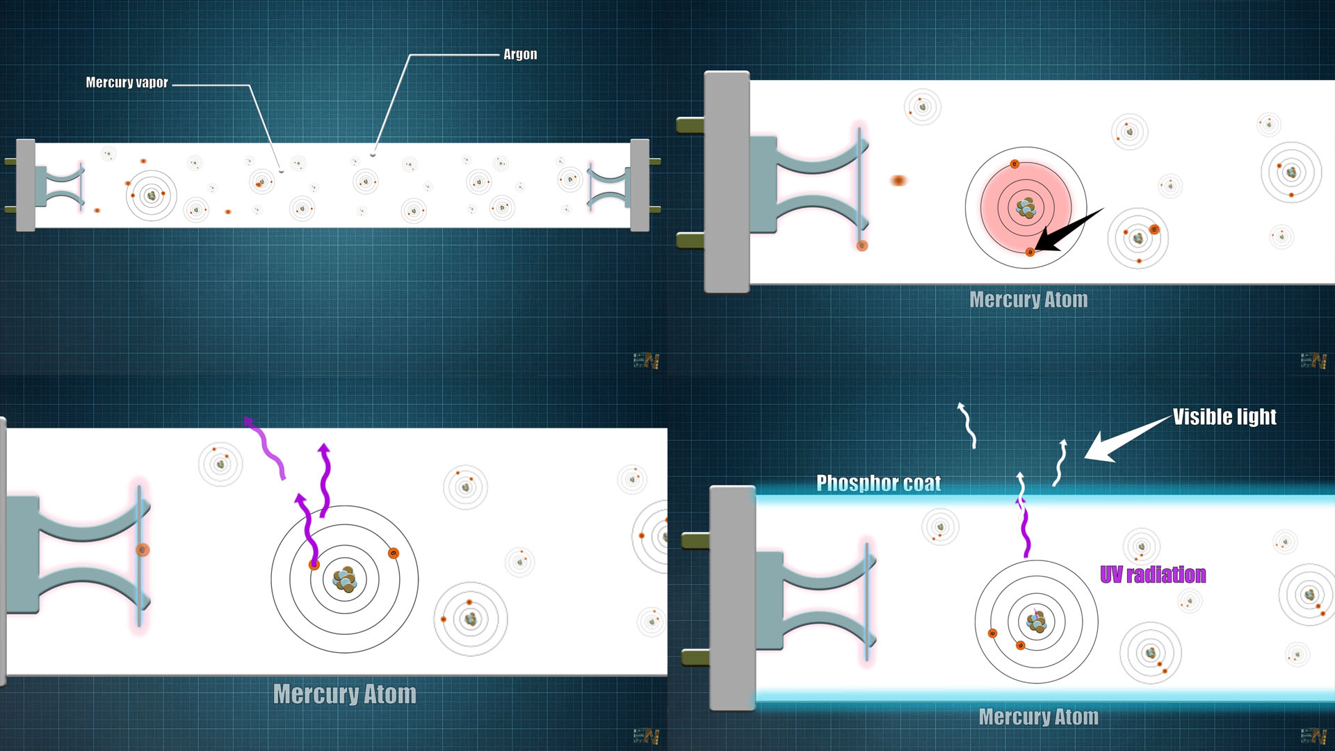
First a little bit of physics. The tubes are filled with Mercury and Argon. When current flows from side to side, the electrons from the electrodes will strike the Mercury and Argon atoms inside the tube, and the energy is transfer to the Mercury atom, and that will push its electrons to a higher orbit. When these electrons fall back to their orbit, they must release that extra energy they have just received. They release the energy in form of Ultra Violate radiation. Now this type of radiation is not useful for us, and is also dangerous, because it could give us skin cancer. That’s why the tube is coated with Phosphor which is a fluorescent material. This material receives the UV radiation and it will convert it into white visible light. That’s how the fluorescent tube works.
But there are a lot of unanswered questions. how can we create the electron flow from one side to the other, why we have two electrodes, why we need an electronic ballast, how to connect it and how does it work. First let me explain you the old circuit with the choke ballast and the starter component and then I will explain you the new electronic ballast step by step.
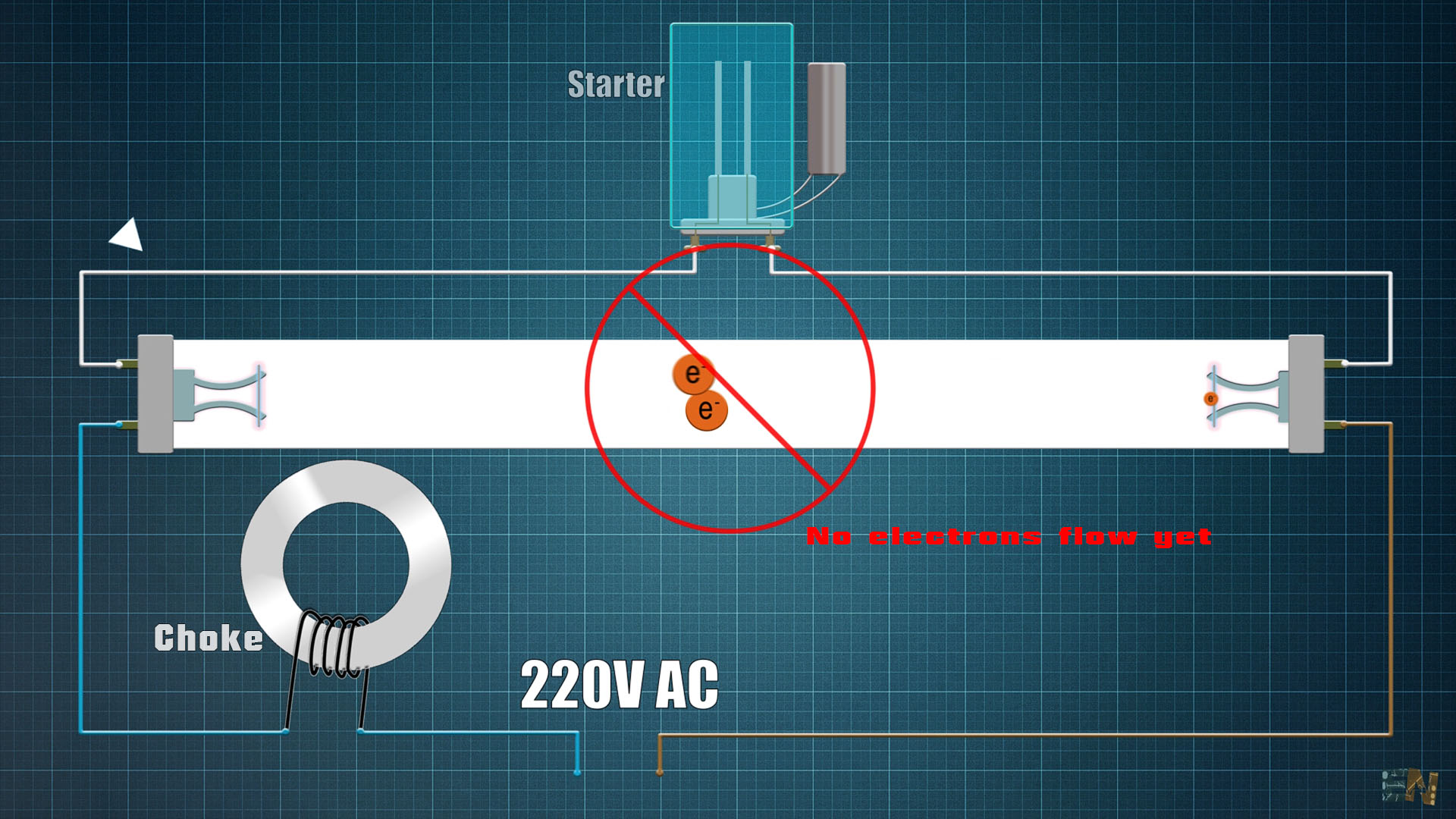
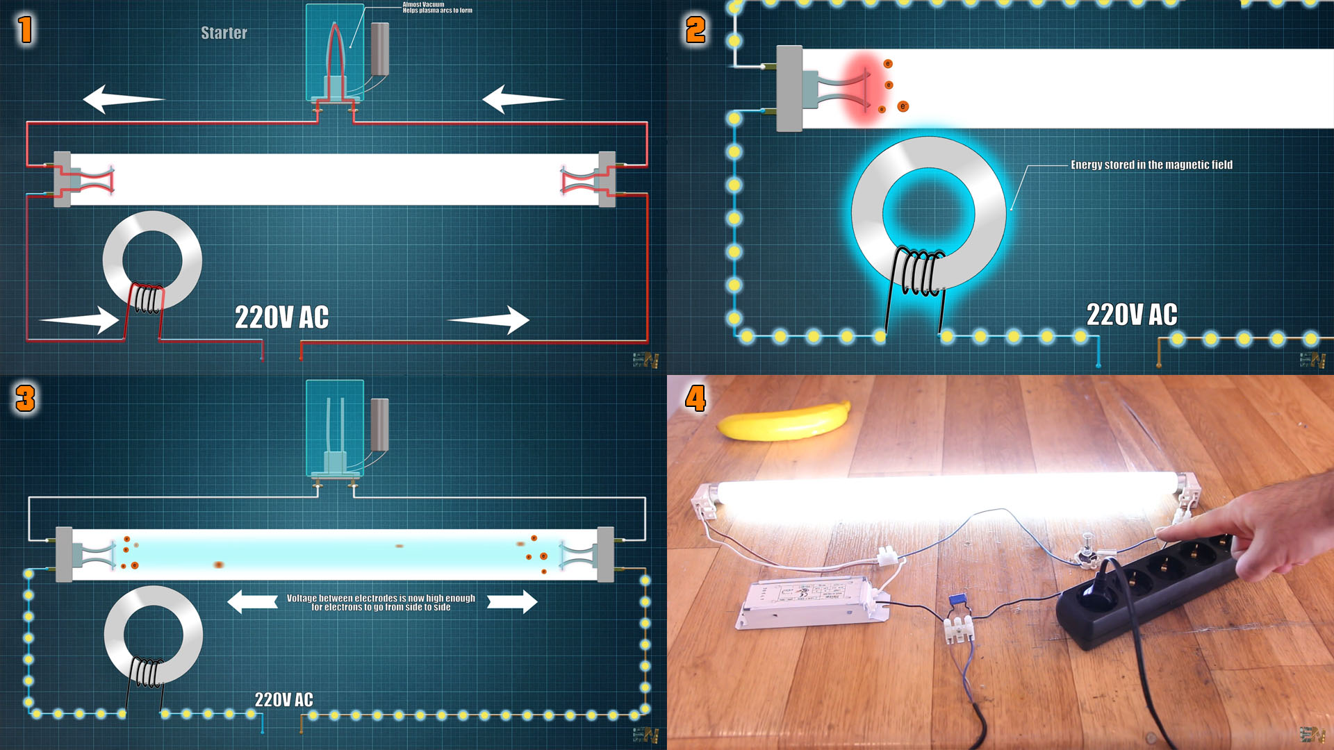
Remember, we have our tube filled with Mercury, and an electrode on each end. We connect our high frequency electricity on one input of each electrode. And the other two inputs are connected together with a so-called starter in series as you can see below. The starter inside has two thin metal contacts that are normally open so they don’t touch each other. On one input, we place the electrical choke which usually is just a coil winded on a ferrite core as you can see below. When we first supply the circuit at let’s say 220V, the circuit is still open, because the connectors inside the starter are not touching each other. So, as you can see, electrons can’t flow from one side to the other in order to make the Mercury radiate UV.
But inside the starter we also have almost vacuum and the metal contacts are close enough for the 220V to create an electrical plasma arc. This plasma arc will heat the connectors just enough to change their shape and connect them one to each other. That will close the circuit and now, a lot of current flows from one side to the other. As you can see in the video below in slow motion, at first, the plasma is created inside the starter and that will bend the metal connectors till they touch each other and clse the circuit and create current flow.
At this point, two things will happen. This current flow will heat up the tungsten filaments and that will, start releasing electrons. But these electrons are still not creating a current path from one side to the other, they have no force pushing them.
But this current flow, will also energize the choke coil (2), by creating a powerful magnetic field around it. But you see, in just a few moments, the metal connectors inside of the starter are getting cold and they will once again separate. So, the powerful magnetic field inside the ballast will now collapse (3) and as you know that will create a huge voltage spike. Now, the voltage differential between the ends, is high enough for the current to arc inside the tube between the electrodes. So now all those electrons are pushed from one side to the other. Once the current path is made, the 220V is enough to keep this current flow going on and on. We only need high voltage spikes at the beginning. Also, once current is flowing, the ballast acts as an impedance in series, so it will lower the volage on the starter, so it won’t flicker any more. So, that’s why we need the starter and the ballast coil and that’s why at the beginning, the old fluorescent tubes were blinking a few times till the current path was created. So, now electrons could flow, hit the Mercury vapor, create UV radiation which will then hit the Phosphor coat on the tube and radiate visible light.
I hope that you like this tutorial. If you consider supporting my work, buy my PCBs on my shop, or maybe consider supporting me on PATREON or if you want, make a PayPal donation. Thank you very much.