If you always wondered which power transistor you should use for your circuits, in this article we will see all the main differences between the IGBT, the BJT and of course, the MOSFFET. As a designer you will have to determine whether to use BJTs or MOSFETs in your application power stage? Or should the designer use IGBTs? Would they work in the design? Would they be better? So there are several choices, but which is the best?
The answer is not straightforward, I would say: “It depends.” And yes, taht's not a very informative or satisfying response but let me explain. The answer it's valid, nonetheless, as the selection is truly dependent on a very wide variety of factors and aspects for the project you want to design. For example, the area of your application that could be motor control, power supply or maybe audio amplifiers and that will influence your choice. The load power modulation technique will also be important and that could be linear, switching control or static. Finall, the operating frequency is important as well. You will need to clearly define your design criteria and approach first, then you can begin to evaluate the advantages and trade-offs of the various available power semiconductors.
Channels or junctions? How many? What type? These and other aspects of the internal device geometry and construction might be one way of looking at power semiconductors, as they are indeed different for the different types of solid-state power devices. But that approach could lead us away from the real point, which is how the device is controlled to vary the load current.
Keep in mind that varying the current through the load in a controlled manner is the primary function (the raison d'être, if you please) of any power semiconductor device. You have a load through which you wish to drive current, and the state of that current flow (either fully on, fully off, or at some predetermined intermediate level) is a function of a signal delivered to the control terminal of the power semiconductor device.
There are several considerations that will steer your choice of power transistor technology. Among them are the magnitude of current your particular load requires, the desired voltage to be applied across the load to achieve that current, and the maximum rate of change of current (dI/dt) and voltage (dV/dt) required.
Succinctly put, there are three key performance parameters that help us understand which power transistor technology might best fit your power stage design: max operating voltage, max operating current, and max switching frequency.
First thing first you have to decide what amount of power your system will need and for taht you ahev to decide:
- Maximum voltage and current
- Maximum frequency of operation
- Reactive parameters of your load (load inductance and load capacitance)
- DC characteristics (and even potential fault characteristics) of your load
Having your load characteristics well-defined means that you are ready to explore the menu of choices for driving your load. The entrée list includes not only popular high-power transistors like MOSFETs, BJTs, and IGBTs, but also more exotic thyristor fare like Triacs and SCRs (for the restricted palate of AC-only or pulsating DC diets, which we will address in a future article).
And, of course, there are the requisite side dishes like ultrafast and Schottky rectifiers (no power design is complete without them, but that's a future article as well). Peruse this menu of solid-state, three-terminal, high-power devices and you'll see that each one controls the load in a different manner.
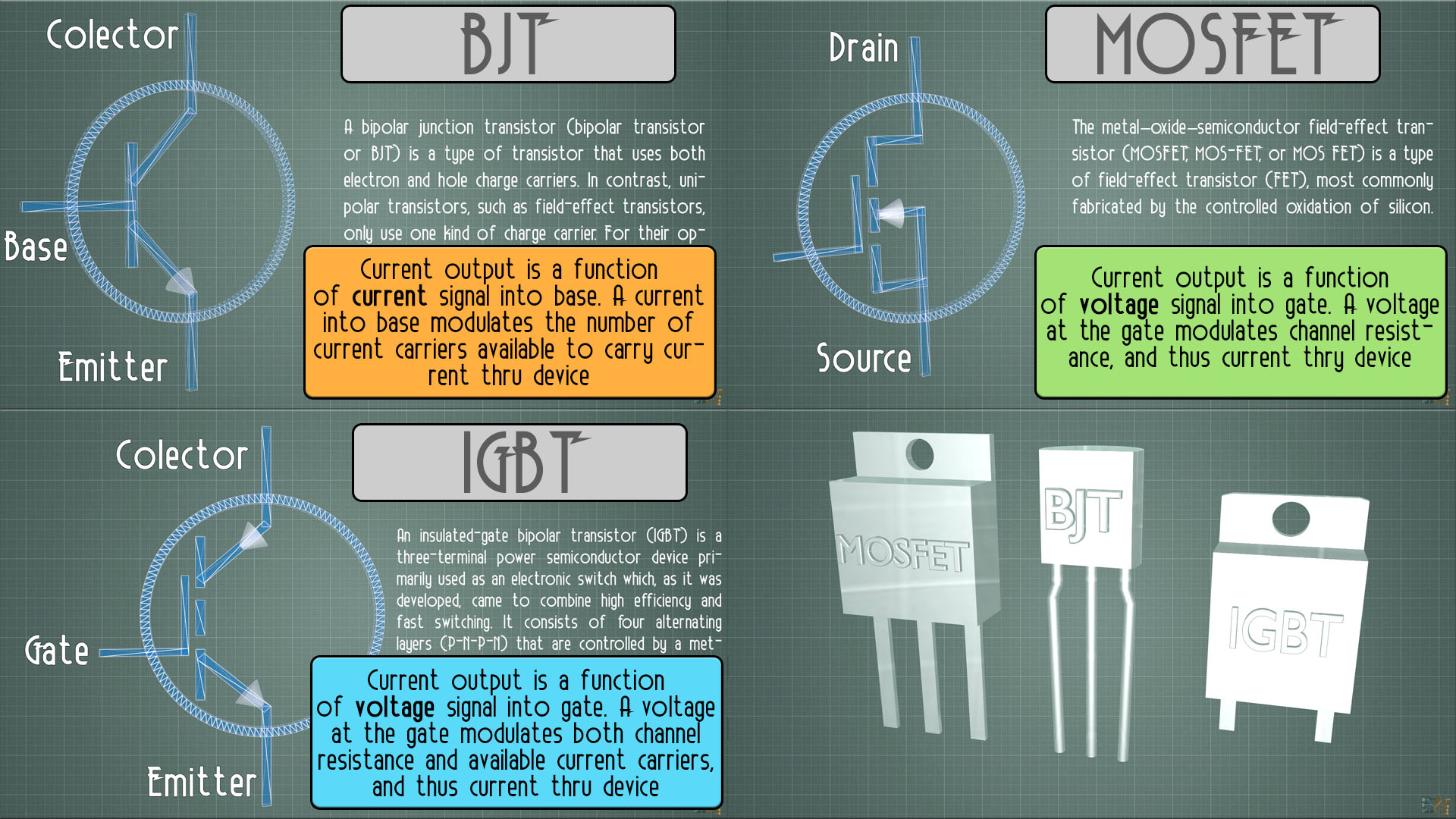
BJT
The BJT varies its output current (defined here as the current flowing through the device from emitter to collector or vice versa) according to its base drive current multiplied by its current gain (hFE). Because of this, the BJT is often described as a current-controlled device.
MOSFET
In contrast, the MOSFET is described as a voltage-controlled device, because its output current varies as a function of a small voltage applied to its gate. Functionally what is happening is that the electrostatic field of the gate is impinging on and affecting the resistance of the source-to-drain channel of the device (hence the term "field-effect transistor").
IGBT
The IGBT can also be considered a voltage-controlled device, as its output current is also a function of a small voltage applied to its gate. It differs functionally, however, in that this control signal voltage modulates a channel resistance which in turn also varies the number of current carriers (both electrons and holes) available to carry current from the emitter terminal to the collector terminal.
Now that I've whetted your appetite, let's examine this triad of power transistor types in a bit more depth. We will focus this closer look by constraining our comparison to their use as high-power switching transistors. This is appropriate as most modern power circuitry applications, even audio, use pulse width modulation (PWM) to control the power into a load, whether it be a transformer, inductor, motor winding, LED, lamp, resistor, or even loudspeaker. This is because PWM is inherently more efficient than linear control/regulation of a load. So, from this focus, we need to look at the power transistors' switching speed performance as well, not just the voltage- and current-handling capabilities.
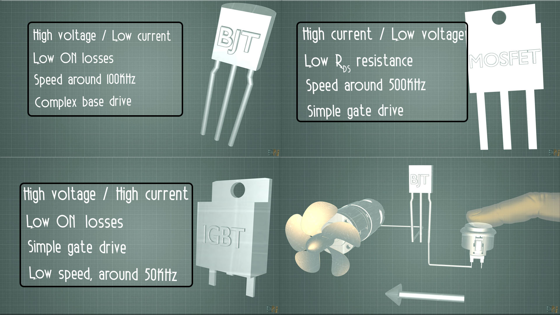
- A bipolar junction transistor designed for use as a high-power transistor will exhibit a fairly modest current gain (with hFE in the single-digit to low double-digit range). And although it is capable of operation as an RF amplifier, the complexities of providing the significant base drive current in a switching application typically limit the use to 100 kHz or less. Within this switching speed range, there are BJTs which can efficiently handle tens of amps while withstanding voltages from several hundred to one thousand volts or more. In terms of comparison to the other two power transistor technologies, we can consider the BJT as a high-voltage, but low-current device.
- Conversely, MOSFETs designed for use as high-power transistors will usually be high-current, but low-voltage devices. Switching frequencies up to 500 kHz are feasible, and there are MOSFETs that can carry several hundred amps, but they are usually limited to voltages much less than 100V. A significant advantage of MOSFETs is that the circuitry required to drive the gate is very simple and low power.
- Interestingly, IGBTs were developed specifically as power transistors, with the aim of combining both high-current and high-voltage. In this role, they have supplanted both BJTs and MOSFETs (as well as thyristors) in many high-power applications. There are quite impressive devices in this technology that can handle currents higher than 1000A while switching several thousand volts! They do have limitations, however, switching speed being a significant one. Manufacturers of these devices work continually to improve the switching speed (specifically by reducing the fall-time) and, in the decades since IGBTs were first commercially introduced, switching speeds have nearly tripled. Nevertheless, practical switching speeds for high-power IGBT power stage designs are seldom more than 50 kHz.
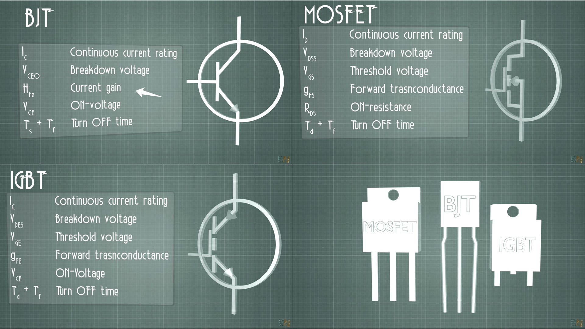
The key parameters for comparing power transistors are shown in the following photo below. Besides evaluating these key parameters, you should also consider both the reactive and fault behaviors of your load when reviewing and comparing power transistor datasheets. For example, IGBTs may latch up (like a thyristor) if subjected to a short-circuit current exceeding their rated short-circuit withstand time (tSC) in microseconds. And inductive loads can create large voltage spikes that may exceed a BJT's breakdown voltage, or overtax the avalanche energy capacity of a MOSFET's body diode (EAS).
So, as you can see in the scheamtic above, we have 3 coils at the output. For now don't mind coil L3, because that will he the output coil that will create the magnetic field. We have 2 coils, L1 and L2 and one capacitors, C1. We will have resonance as before but this time that will be different and will never stop. As you can see we also have two diodes, D1 and D2 that are connected to the gate of two transistors, T1 and T2. When the signal is first oscillating on C1 there will be a positive voltage on one side of C1 and a negative voltage on the oher side of C1. So one diode will allow current flow and the other one won't. So, one transistor willl eb turned on and the other will be off. But just moments after, because of this process, the polarity on C1 will change and that will activate the second transistor and turn off the other one. And this process will repeat on and on and that will change the current flow inside the L3 coil, because as you can see one enf of that coil is connected to 15V and the other end will be connected to negative or positive and by that creating an oscillating current. That will create the oscillating magnetic field.
We have discussed the three key performance parameters that help us understand which power transistor technology might best fit your power stage design. To reiterate, these are max operating voltage, max operating current, and max switching frequency. These and other datasheet parameters provide the designer with the technical information needed to make thoughtful design decisions. But often designers would also like to know how these devices are commonly utilized in commercial/industrial market applications, as this provides insight into how other designers have evaluated the performance and cost trade-offs.
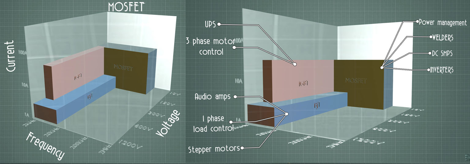
This graph illustrates the power transistor applications space in three dimensions. Each axis of the graph represents one of the three key performance parameters, and each power transistor technology is represented by a different color arrow.
For example, at the top of the graph, you will note a bar representing small electric vehicle applications (e.g., golf carts, electric forklifts). The motor controllers in these typically operate at voltages from 48V to 72V and currents up to several hundred amps, and they commonly utilize MOSFETs PWM'ing the motor at frequencies around 20 kHz (comfortably above human hearing).
As a caveat, the data driving this graph is properly considered anecdotal, as it is drawn from my own personal observation. I have provided it in hopes of sharing my insight from four decades in the industry working with a wide range of customers and applications.
Conclusion
You should now have a good idea of your options and where to start when choosing the type of power transistor to use in your next high-power design. Keep an eye out for future articles on related topics.