Designing and building this tiny violin was a fun way to experiment with building my own microcontroller development board from scratch, as I've been meaning to do for a while. So I'll be documenting the whole process here, from PCB design to programming the microcontroller.
The first step was choosing the microcontroller I was going to use, based on the functionalities I wanted my violin to have. I needed at least one PWM pin for the piezoelectric buzzer and another two digital pins for the LEDs and for the push-button, so the ATtiny85 turned out to be the perfect fit.
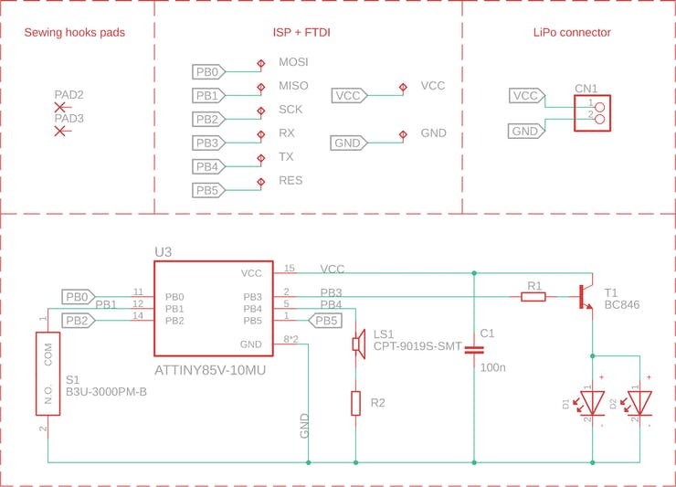
The circuit schematic is fairly simple. The ATtiny85 controls two LEDs and a piezoelectric buzzer, and I also added a push-button for switching between songs. The whole circuit is powered by a 3.7V LiPo battery.
I wanted to make the PCB as small as possible, in order to be able to use it as a badge, so I found the tiniest microcontroller package (MLF-20).
As an extra feature, I also connected the strings of the violin to an analog input of the microcontroller, in order to actually be able to play the violin by touching the strings with a conductive material.
I use Eagle CAD for designing my PCBs, and Gordon Williams' SVG to Eagle converter is always my go-to tool when I need custom PCB outlines. I traced the outline of a violin in Inkscape and then converted it to an Eagle script with this tool.
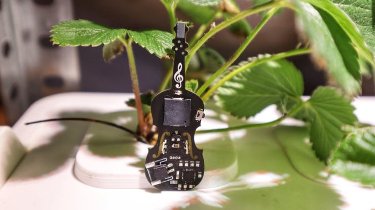
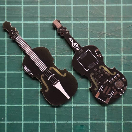
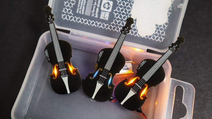
In order to obtain the shine-through effect for the F-holes of the violin, I placed side-view LEDs on the back of the PCB and I used the Top and Restrict layers to remove copper and solder mask from that area.
These are the PCBs I ordered from JLCPCB. The silkscreen is very detailed and I think the matte black solder mask suits the violins perfectly! I forgot to remove the order number this time, but JLCPCB has an option to do that when ordering PCBs.
I've added the Gerber files and the Eagle CAD files to this Github repository if you want to order it as well.
I'm looking forward to improving a few things in the future iterations:
Hope you liked my project! Drop a comment if you have any questions. ^^