So, I've made a video with some radio modules you could use. In this case we will see the LoRa radio module with SPI serial communication. See the connections below, download the example code and test if it works. You will need the LoRa library as well so download that from the links below. You need two modules, an LED and a potentiometer and we will send just one byte of data, 0 to 255 values. The range for this module could be up to 5Km abut we need a lot of pins to use this.
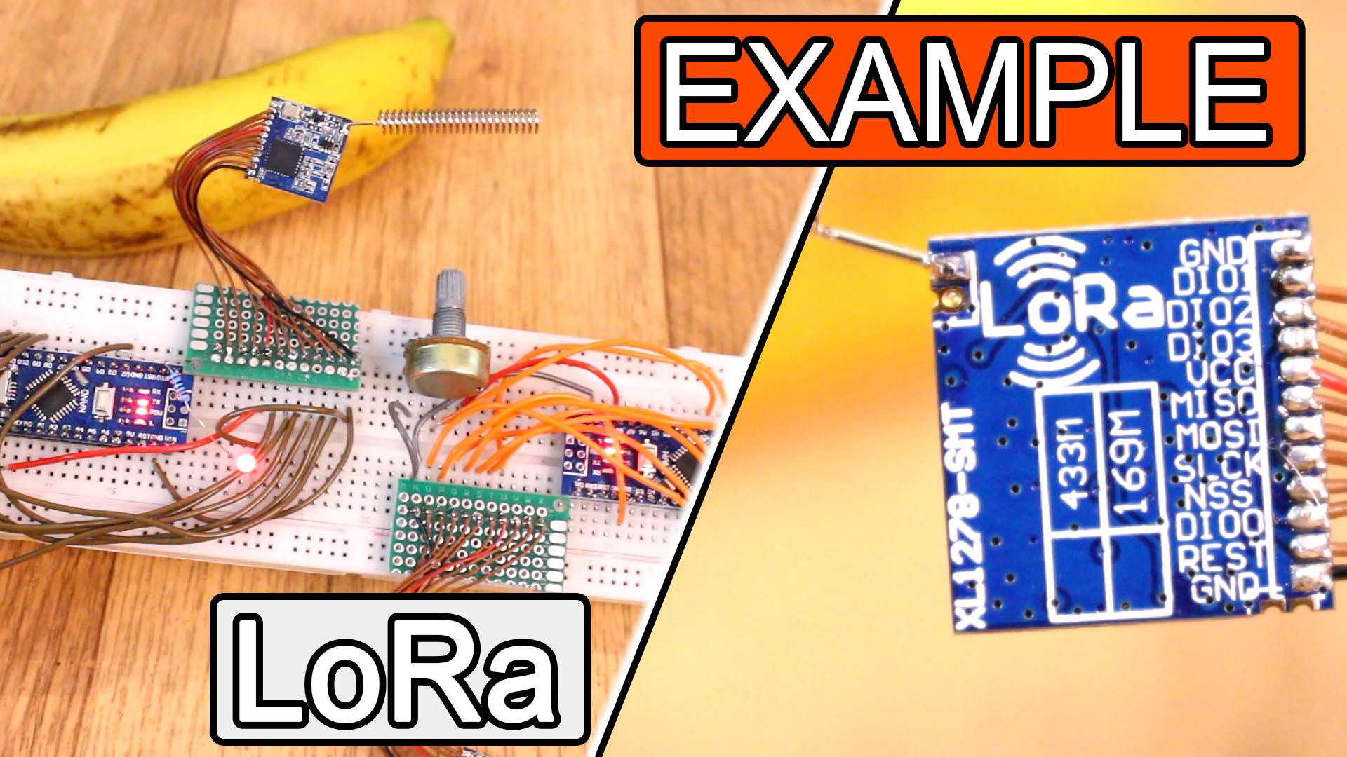
Ok guys, now let’s take a look at the LoRa module. As I said in a previous tutorial, I’ve used this module for a very short time. LoRa is a robust, low-power, long-range wireless protocol developed by Sem tech. It could operate at 433MHz or 915MHz. According to its datasheet, it is a 5 - 6KM wireless transceiver module, and I say according to the datasheet, because I haven’t made any range tests and I always used this module below 100 meters and never had problems with the transmission. I’m using a LoRa module with the SX1278 chip which is the tiny SMD IC and we have to add an antenna designed for 433MHz as well to the antenna port. The price on eBay for this module is around 4 dollars as well and the module will also include the antenna.
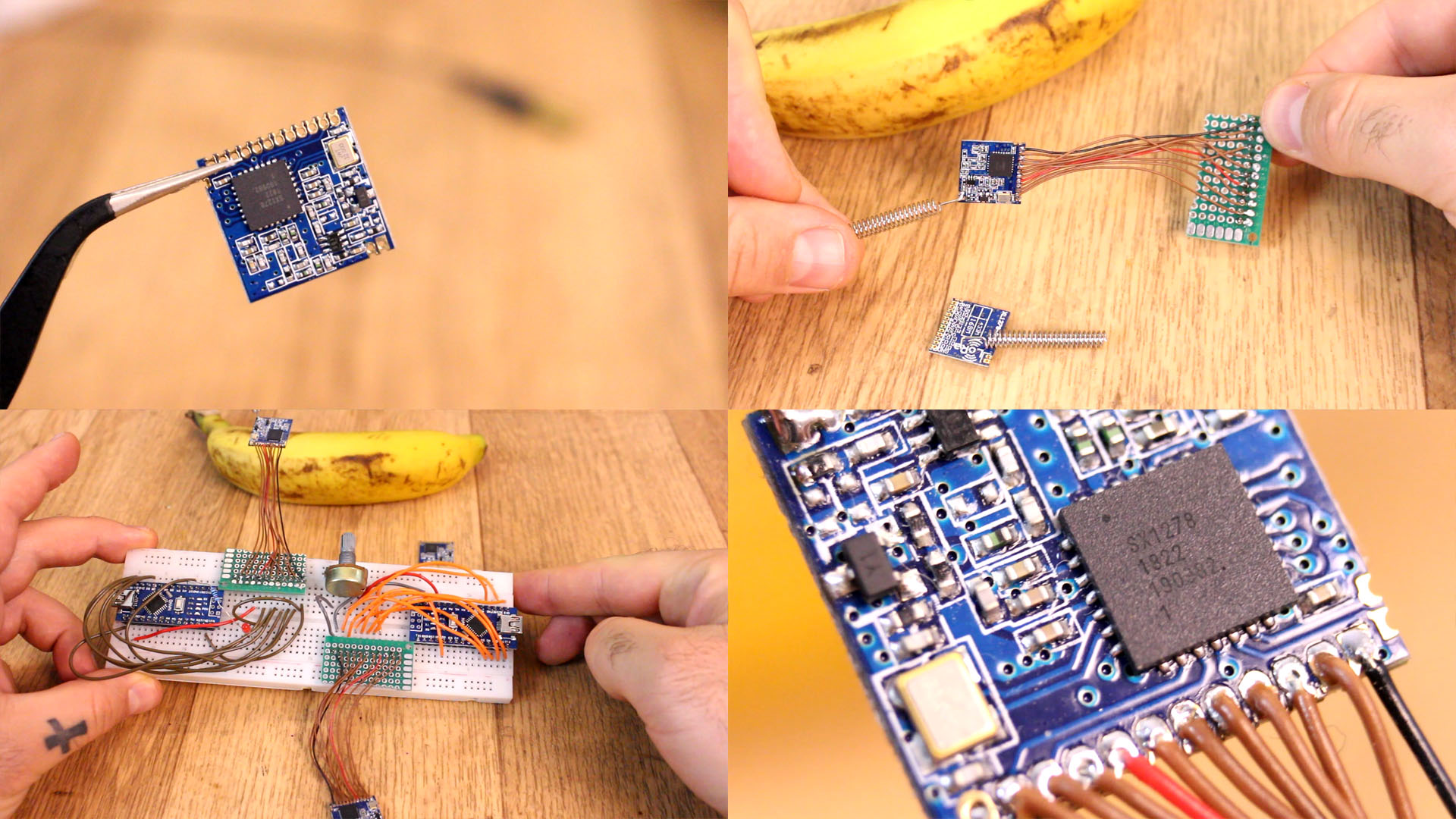
To communicate with this module we will use once again an SPI communication, but this time we need a few more pins. Again we have the MISO and MOSI, clock but we also have a reset pin, enable, data input output, and GND and 3.3V volts. In this case, even it uses a 3.3V input, the module has lower power and it worked ok with an Arduino NANO till now. So, I first solder wires and pins to both modules in order to eb able to place these on a breadboard. Now I make all the connections to the Arduinos as in the schematic.
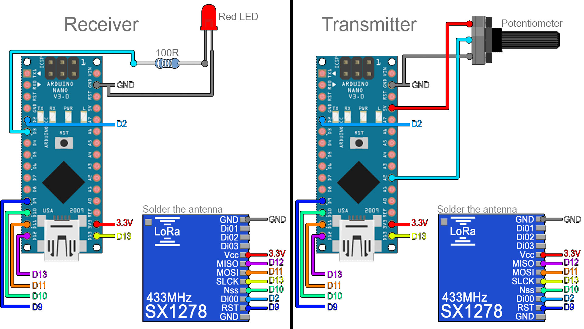
The schematic is simple but with a lot of pins. We have 2 Arduino NANO and we will use 3.3V from the Arduino in this case. If this doesn't work, connect an external 3.3V supply and share ground. Anyway, connect the SPI pins and add a potentiometer, and LED and a resistor. Upload the codes below to the transmitter and receiver and read the comments in the code for more. Test if it works and you could change the brightness of the LED using the radio connection.
Here we have the transmitter code. You will need a library for this module so download that from the code link below and install it to the Arduino IDE. Uplaod this code to the Arduino with the potentiometer. Read the comments in the code for more. Copy or download the code from below.
/* 1byte LORa SX1278 TRANSMITTER example.
/* Tutorial link: http://electronoobs.com/eng_arduino_tut97.php
 * Code: http://electronoobs.com/eng_arduino_tut97_code1.php
 * Scheamtic: http://electronoobs.com/eng_arduino_tut97_sch1.php
 * Youtube Channel: http://www.youtube/c/electronoobs
 *
  Module SX1278 // Arduino UNO/NANO
    GND         ->   GND
    Vcc         ->   3.3V
    MISO        ->   D12
    MOSI        ->   D11
    SLCK        ->   D13
    Nss         ->   D10
    Di00        ->   D2
    RST         ->   D9
 */
#include <SPI.h>
#include <LoRa.h> //Download here: http://electronoobs.com/eng_arduino_LoRa_SX1278.php.php
int pot = A2;

void setup() {
  Serial.begin(9600);
  pinMode(pot,INPUT);

  while (!Serial);
  Serial.println("LoRa Sender");
  if (!LoRa.begin(433E6)) { // or 915E6, the MHz speed of yout module
    Serial.println("Starting LoRa failed!");
    while (1);
  }
}

void loop() {
  int val = map(analogRead(pot),0,1024,0,255);
  LoRa.beginPacket();
  LoRa.print(val);
  LoRa.endPacket();
  delay(50);

}
Here we have the receiver code now. Uplaod this code to the Arduino with the LED. Read the comments in the code for more. Copy or download the code from below.
/* 1byte LORa SX1278 TRANSMITTER example.
/* Tutorial link: http://electronoobs.com/eng_arduino_tut97.php
 * Code: http://electronoobs.com/eng_arduino_tut97_code2.php
 * Scheamtic: http://electronoobs.com/eng_arduino_tut97_sch1.php
 * Youtube Channel: http://www.youtube/c/electronoobs
 *
  Module SX1278 // Arduino UNO/NANO
    GND         ->   GND
    Vcc         ->   3.3V
    MISO        ->   D12
    MOSI        ->   D11
    SLCK        ->   D13
    Nss         ->   D10
    Di00        ->   D2
    RST         ->   D9
 */

#include <SPI.h>
#include <LoRa.h>   //Download here: http://electronoobs.com/eng_arduino_LoRa_SX1278.php.php
int LED = 3;
String inString = "";    // string to hold input
int val = 0;

void setup() {
  Serial.begin(9600);
  pinMode(LED,OUTPUT);

  while (!Serial);
  Serial.println("LoRa Receiver");
  if (!LoRa.begin(433E6)) { // or 915E6
    Serial.println("Starting LoRa failed!");
    while (1);
  }
}

void loop() {

  // try to parse packet
  int packetSize = LoRa.parsePacket();
  if (packetSize) {
    // read packet
    while (LoRa.available())
    {
      int inChar = LoRa.read();
      inString += (char)inChar;
      val = inString.toInt();
    }
    inString = "";
    LoRa.packetRssi();
  }

  Serial.println(val);
  analogWrite(LED, val);
}
Now you are able to control the LED using radio connection. These modules could get up to 5Km according to their datasheet. That's it for this module. I hope you are able to use it. If not, comment below and ask for help. Keep up!