In this tutorial I've merged a few sensors together in order to measure distance using infrared light sensors, measure length using a rotary encoder and a 3D printed wheel, measure level with an IMU module but also angles with that same module and finally measure RPMs with another kind of IR sensor. Everything is inside a 3D printed case that I've designed and we have a battery and a charging module with USB as well. To control the modes and more we have 4 touchless buttons based on capacitance that could be below the plastic case. To print the value we use an OLED display and the case also has a laser module pointer. Let's see how to make this.
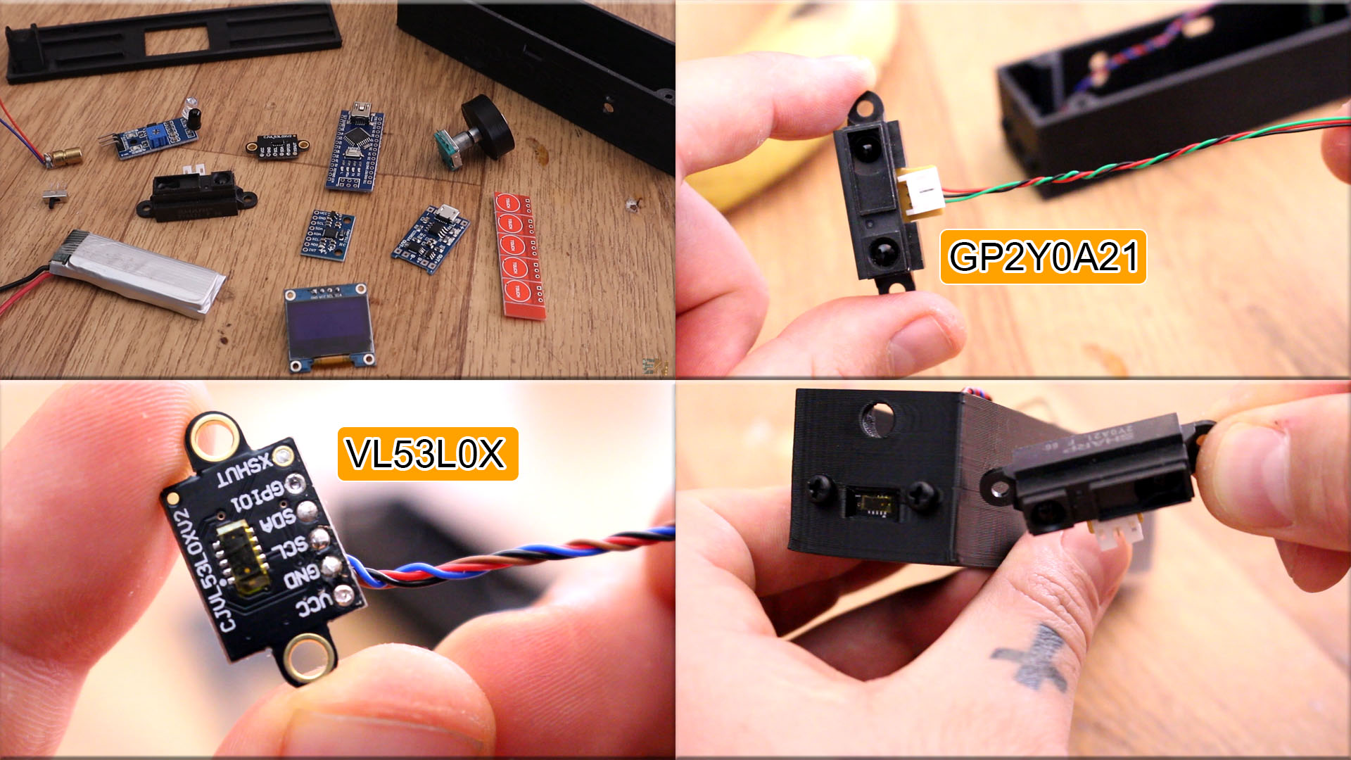
Ok guys, let's start this tutorial and first look at what we need. Let's takea look at the electronics first and then we can see the 3D printed case. Ok, so I want to measure distance. For that I've selected 2 sensors adn this is why. One has good range up to 80cm but the other sensor has better precision but only up to 20cm. So I've used the SHARP gp2y0a21 to measure distacne up to 80cm with a resolution of centimeters. Then I've used the VL53L0X sensor to measure distance up to 20cm with a millimeters precision. Both are using infrared light to measure distance but the VL53L0X is laser based and has better precision.
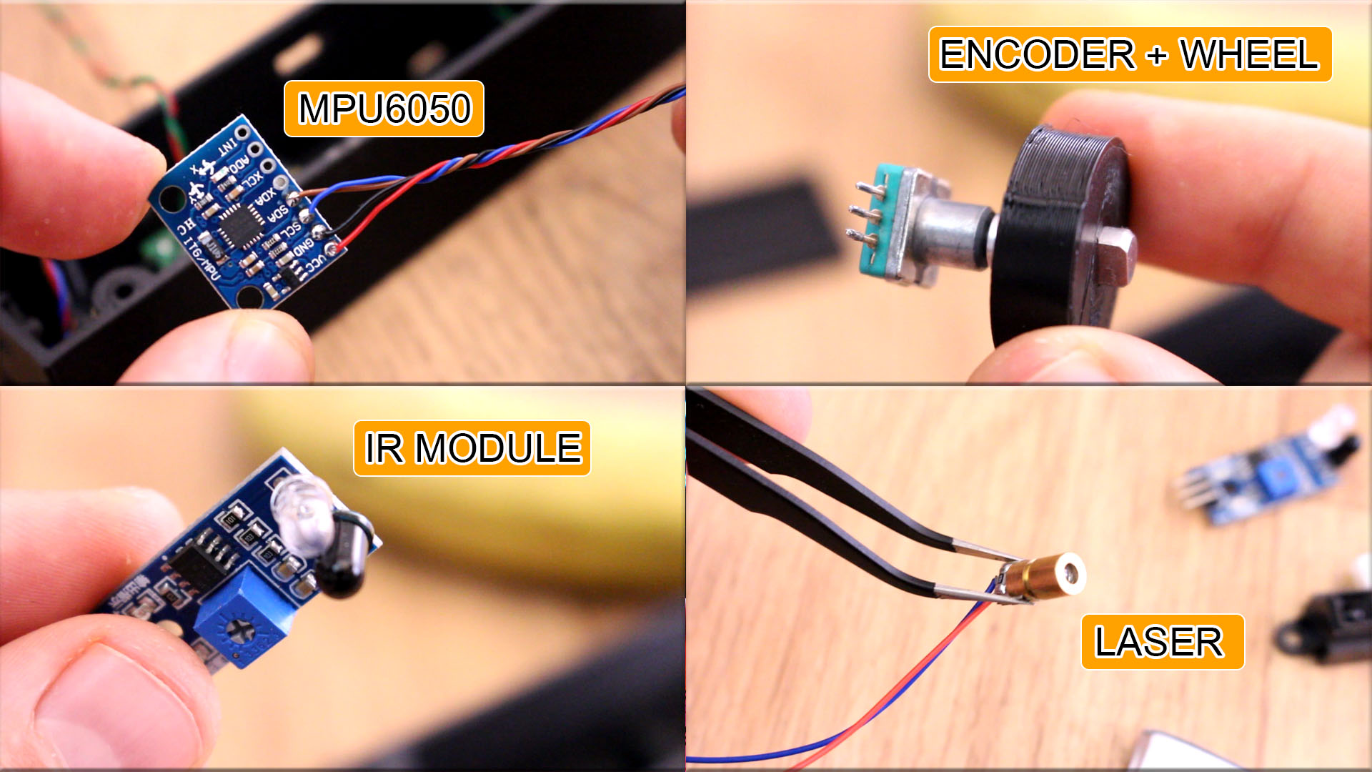
Ok, now I want to measure angles and detect level. For that I'll be using the MPU6050 gyro and accelerator module. With this module I can measure angle adn then make all sort of operations. This will be palced in the middle of the case. I also want to mesure length and for taht I'll usie an rotary encoder module and a 3D printed wheel. I know the perimeter of the wheel so when it spins I could measure length. Ok, I also want to measure RPMs and for taht I've used another infrared module with an IR LED and IR phototransistor. With this and a white strip on the rotating shaft I can count rotations. I will use a laser pointer module in order to mesure angles between the meter and a point on the oposite wall.
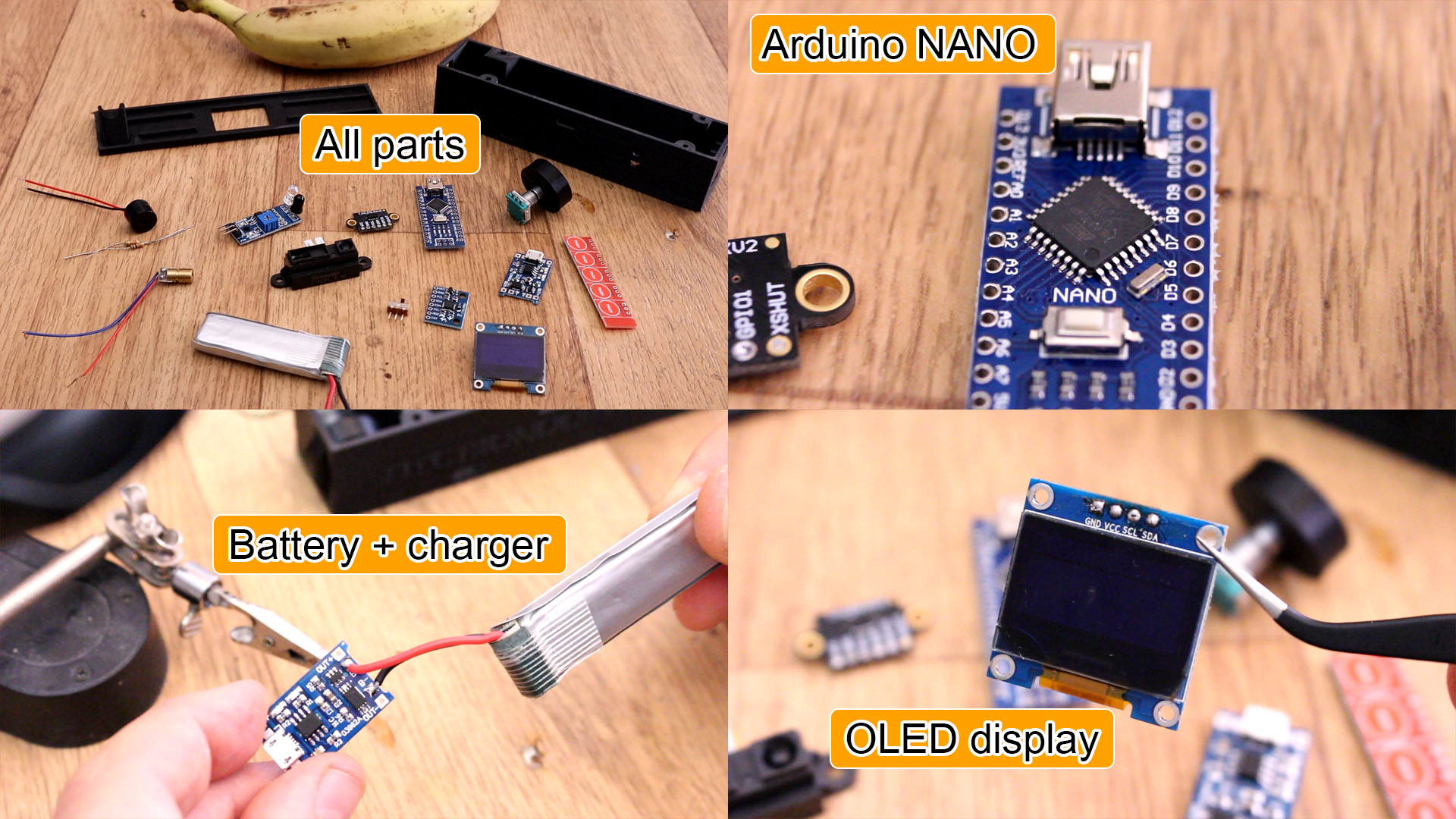
Now let's check the final parts we need. Of course we need an Arduino. Then we need 4 touchless buttons based on capacitance change. We need a 3.7V battery and a charging module with USB connector. Finally we need an OLED dsiplay, a slider switch to turn the meter on an off and a buzzer for sound notifications. We will of course need wires, solder and a soldering iron and then the 3D printed case.
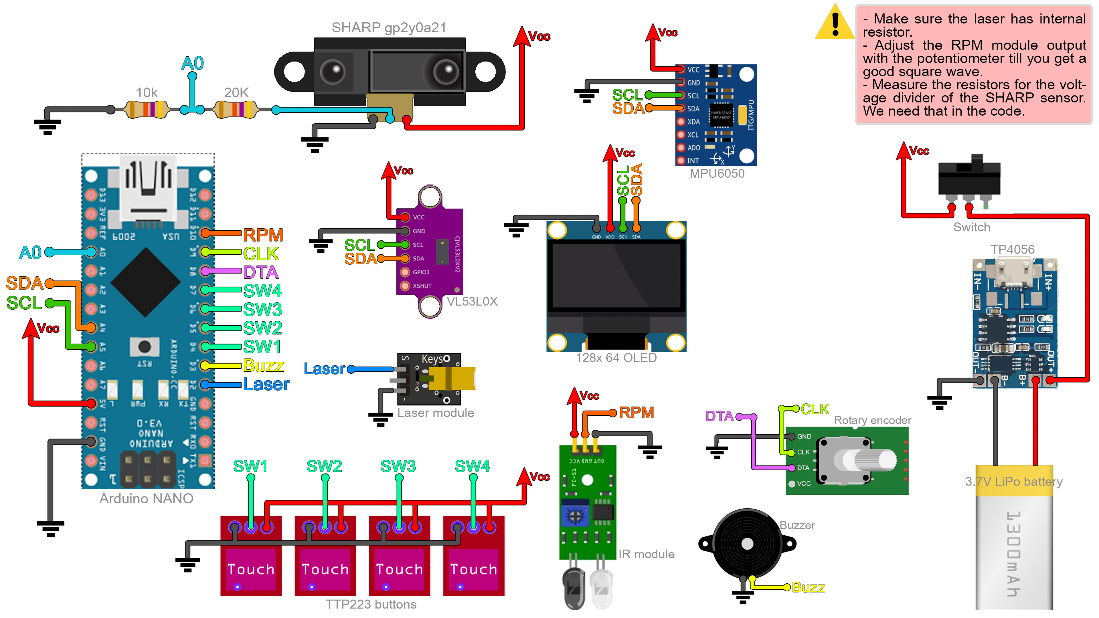
As you can see below the scheamtic has a lot of connections for all the sensors. The OLED display with the MPU6050 and the VL5L0X are using i2c communication and those will eba ll connected to A4 and A5 pins of the Arduino for data and clock. The SHARP sensor has a voltage divider at the output. I must use the internal voltage refference of 1.1V that the ATmega328 has inside in order to make the analogRead. That's because I'm using a 3.7V battery and if I'm not using the internal 1.1V refference for analogRead, the value would change together with the battery voltage. Measure the voltage divider values and place those in the code. Connect all the modules to the digital pins. Make sure the laser has a current limiting resistor otherwise you will burn it.
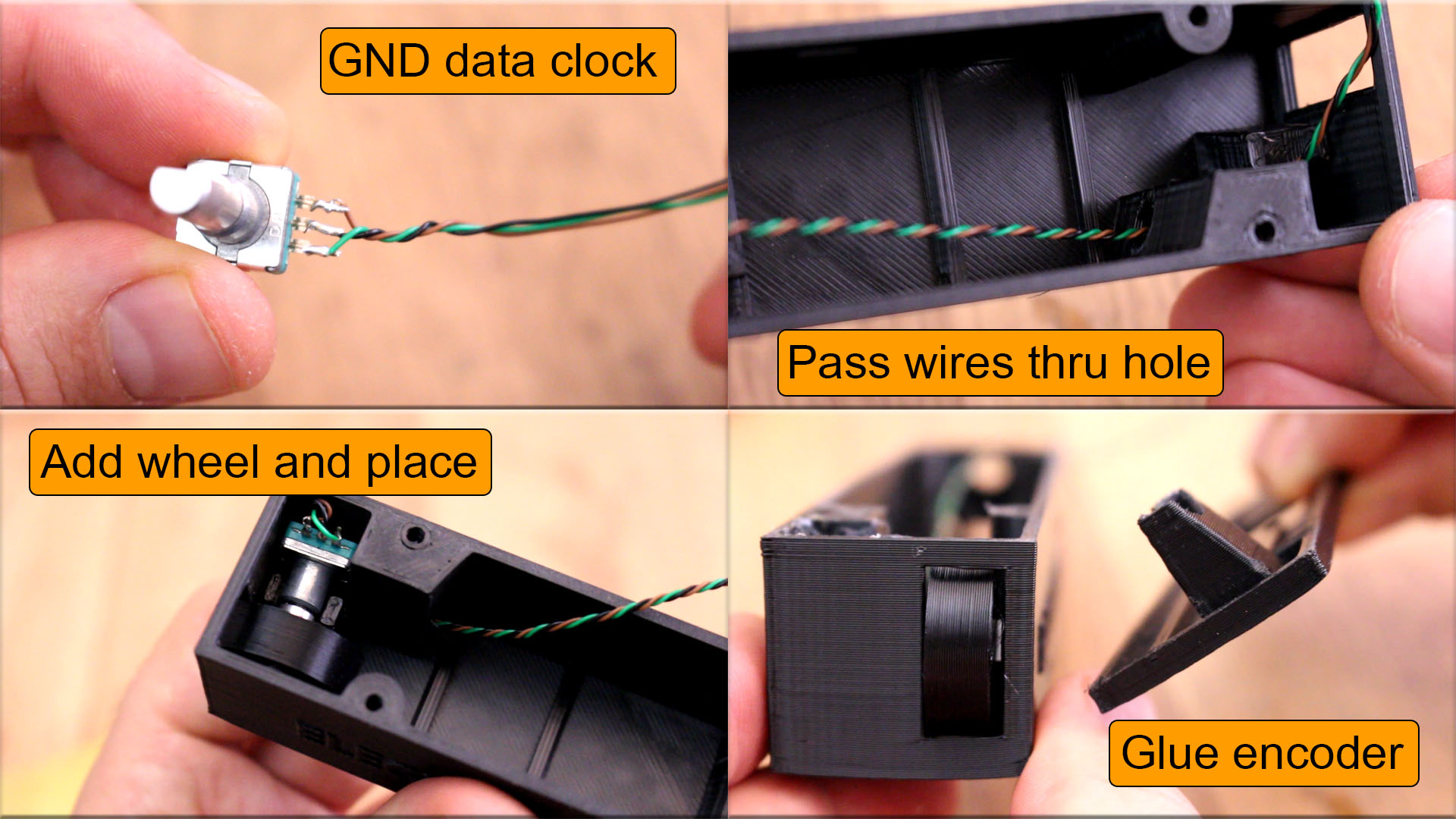
First I add the rotary encoder that will be used to measure length. For that we need the 3D printed wheel and we need to know the diameter of the wheel, taht's important for later calculations in the code so measure the diameter. Solder 3 wires for ground, data and clock. Add the plastic wheel and then pass the wires thru the hole that the case has and place the encoder whith the wheel in its place. Glue the encoder with hot glue but don't add glue on the top side of the encoder because that part will be push down by the top part of the 3D printed case.
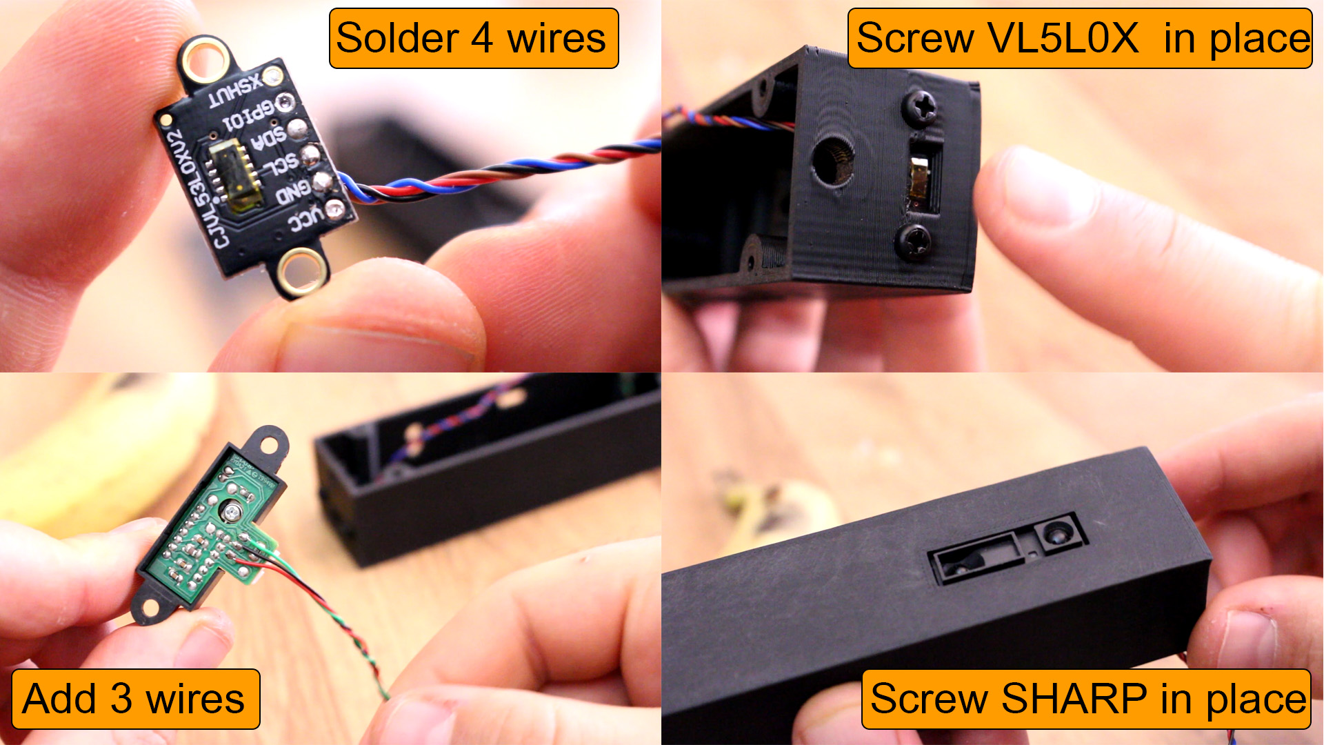
Now solder wires to both VL5L0X and SHARP 2YA021 modules. One needs 4 wires and the other 3. Screw the VL5L0X on one side of the case with the sensor facing the outside of the case. Then screw in place the SHARP sensor and make sure that it doesn't get out on the exterior of the case becasue if it dose, it will unlevel the meter and we need the bottom aprt to be flat for the level mode. If it dose, just add some washers and push it upwards a little bit.