
In this project we take a look over the concepts of SPWM signal which is a width modulated signal but with certain values on souch a way that we could create a sine shape wave at the output. This with some MOSFETS could result in a sinw wave inverter. We will also talk a bit about the concept of feedback for this circuit.
We all know PWM signal or pulse width modulation. That means we modulate the width of a square signal and by that we could control power. But, this width in case of normal PWM is alweys the same. In case of SPWM or sinusoidal pulse width modulation, the width of the signal is increasing and decreaseing and my that simulating the curve of the sine wave. With small width pulse, the output will incrase a little bit and that represents the zone after the 0 cross of the sine wave. Then with bigger widths, the output is getting bigger and bigger and then it starts to get lower, just as a sine wave. Uisng two mosfets, we could get both the positive and negative sides of the sine wave.
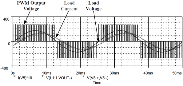
In the figure below we can see a bit better how the width of the SPWM can create a good sinusoidal shape at the output. And that's exactly what we will do in this project. We will use the Arduino to generate this SPWM signal at 50Hz, just as a normal house outlet signal. We apply this signal to the driver and then to the MOSFETs. These will be connected to the transformer which will incrase the voltage but also create the sine shape signal.
Ok, so first we look over this basic inverter schematic that has no feedback. That means the load can change the output and we won't be able to tell. Any way, we have a driver connected to the MOSFET bridge. The signal will be applied by an Arduino that will create an SPWM signal at 50 or 60 Hz. Take a look over the schematic and let's talk about SPWM signal as well.
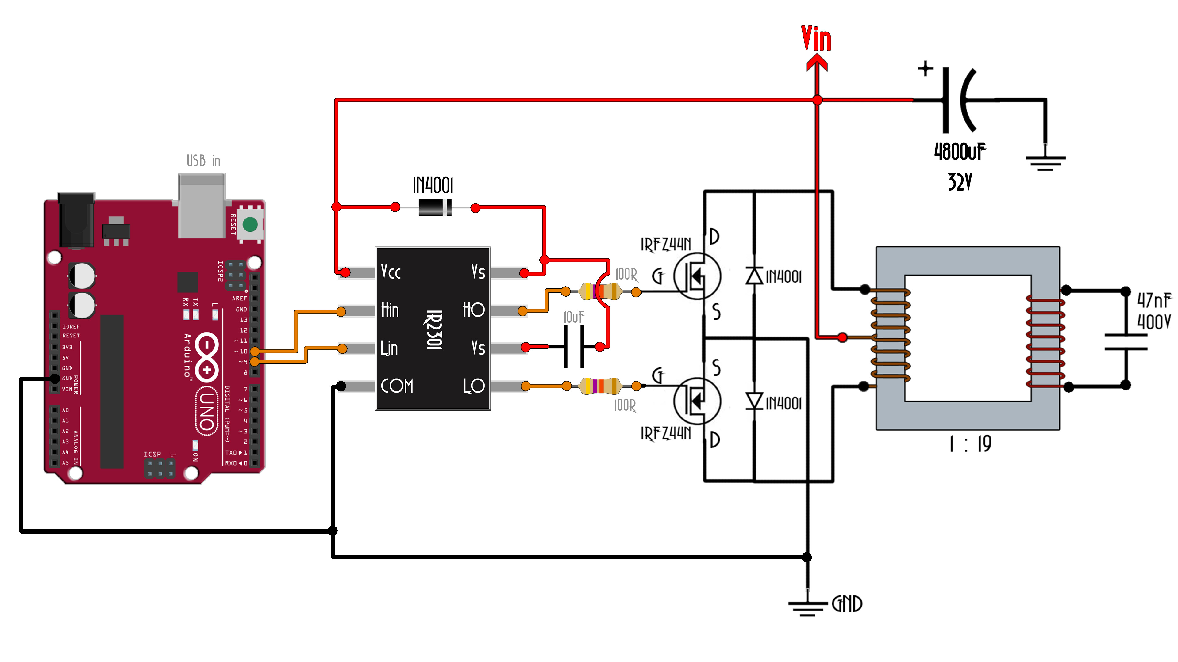
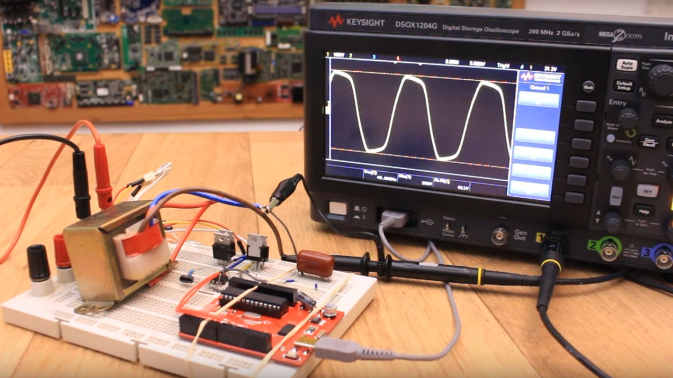
See the schematic above for this part and also the part list in order to know what we need. The Arduino creates the SPWM signal connected to a dual driver. This dual MOSFET driver will control the MOSFET bridge. The power is applied to a transformer that has a dual coil input and a single coil output. In this way we can create positive and negative parts of the wave. Cnnect everything on the breadboard and supply 12V and observe the output. Remember to add a high voltage capacitor at the output, otherwise the output will be just high voltage noise. Is time to see the code that generates the SPWM signal.
SO how can we create this SPWM signal? Well, with the Arduino, in the code, we make two pins to be PWM pins by setting some registers, TCCR1B and TCCR1A. Now e have to change the width of this signal by changing the value of the OCR1A. But what values we need to use. Well, these are not random values, they musy follow a sine shape curve. So, by knowing the range of the min and max of the PWM signal and using an Excel sheet, we could create values of a sine curve from 0 to 180 degrees. We store those values in a vector as you can see below in the example bit of code.
int lookUp1[] = {
50 ,100 ,151 ,201 ,250 ,300 ,349 ,398 ,446 ,494 ,
542 ,589 ,635 ,681 ,726 ,771 ,814 ,857 ,899 ,940 ,
981 ,1020 ,1058 ,1095 ,1131 ,1166 ,1200 ,1233 ,1264 ,1294 ,
1323 ,1351 ,1377 ,1402 ,1426 ,1448 ,1468 ,1488 ,1505 ,1522 ,
1536 ,1550 ,1561 ,1572 ,1580 ,1587 ,1593 ,1597 ,1599 ,1600 ,
1599 ,1597 ,1593 ,1587 ,1580 ,1572 ,1561 ,1550 ,1536 ,1522 ,
1505 ,1488 ,1468 ,1448 ,1426 ,1402 ,1377 ,1351 ,1323 ,1294 ,
1264 ,1233 ,1200 ,1166 ,1131 ,1095 ,1058 ,1020 ,981 ,940 ,
899 ,857 ,814 ,771 ,726 ,681 ,635 ,589 ,542 ,494 ,
446 ,398 ,349 ,300 ,250 ,201 ,151 ,100 ,50 ,0 ,
0 ,0 ,0 ,0 ,0 ,0 ,0 ,0 ,0 ,0 ,
0 ,0 ,0 ,0 ,0 ,0 ,0 ,0 ,0 ,0 ,
0 ,0 ,0 ,0 ,0 ,0 ,0 ,0 ,0 ,0 ,
0 ,0 ,0 ,0 ,0 ,0 ,0 ,0 ,0 ,0 ,
0 ,0 ,0 ,0 ,0 ,0 ,0 ,0 ,0 ,0 ,
0 ,0 ,0 ,0 ,0 ,0 ,0 ,0 ,0 ,0 ,
0 ,0 ,0 ,0 ,0 ,0 ,0 ,0 ,0 ,0 ,
0 ,0 ,0 ,0 ,0 ,0 ,0 ,0 ,0 ,0 ,
0 ,0 ,0 ,0 ,0 ,0 ,0 ,0 ,0 ,0 ,
0 ,0 ,0 ,0 ,0 ,0 ,0 ,0 ,0 ,0};
Now there are a lot of "0" as well and that's because when one MOSFET is active and with SPWM signal, the other one is turned off an vice-versa. That's why in the code you will see two vectors, one that starts with zeros and ends with SPWM values and one that starts with SPWM values and ends with zeros.
Now, in the ISR interrumption, all we have to doo is to change the PWM width for both pin after each loop. By changing the ISR speed, we change the frequency of the output signal, in this case a 50Hz signal.
ISR(TIMER1_OVF_vect){
    static int num;
    // change duty-cycle every period.
    OCR1A = lookUp1[num];
    OCR1B = lookUp2[num];

    if(++num >= 200){ // Pre-increment num then check it's below 200.
       num = 0;       // Reset num.
     }
}


