
This is the code for PWM receiver of the Arduino based radio controller project. Make sure you also install the needed library for the NRF24 module. Download those from below. Install the library, compile and uplaod the code to the Arduino. Downlaod the zip file or copy+paste from below. Read all comments in the code!
/* Receiver code for the Arduino Radio control with PWM output
* Install the NRF24 library to your IDE
* Upload this code to the Arduino UNO, NANO, Pro mini (5V,16MHz)
* Connect a NRF24 module to it:
Tutorial here: https://www.electronoobs.com/eng_arduino_tut86.php
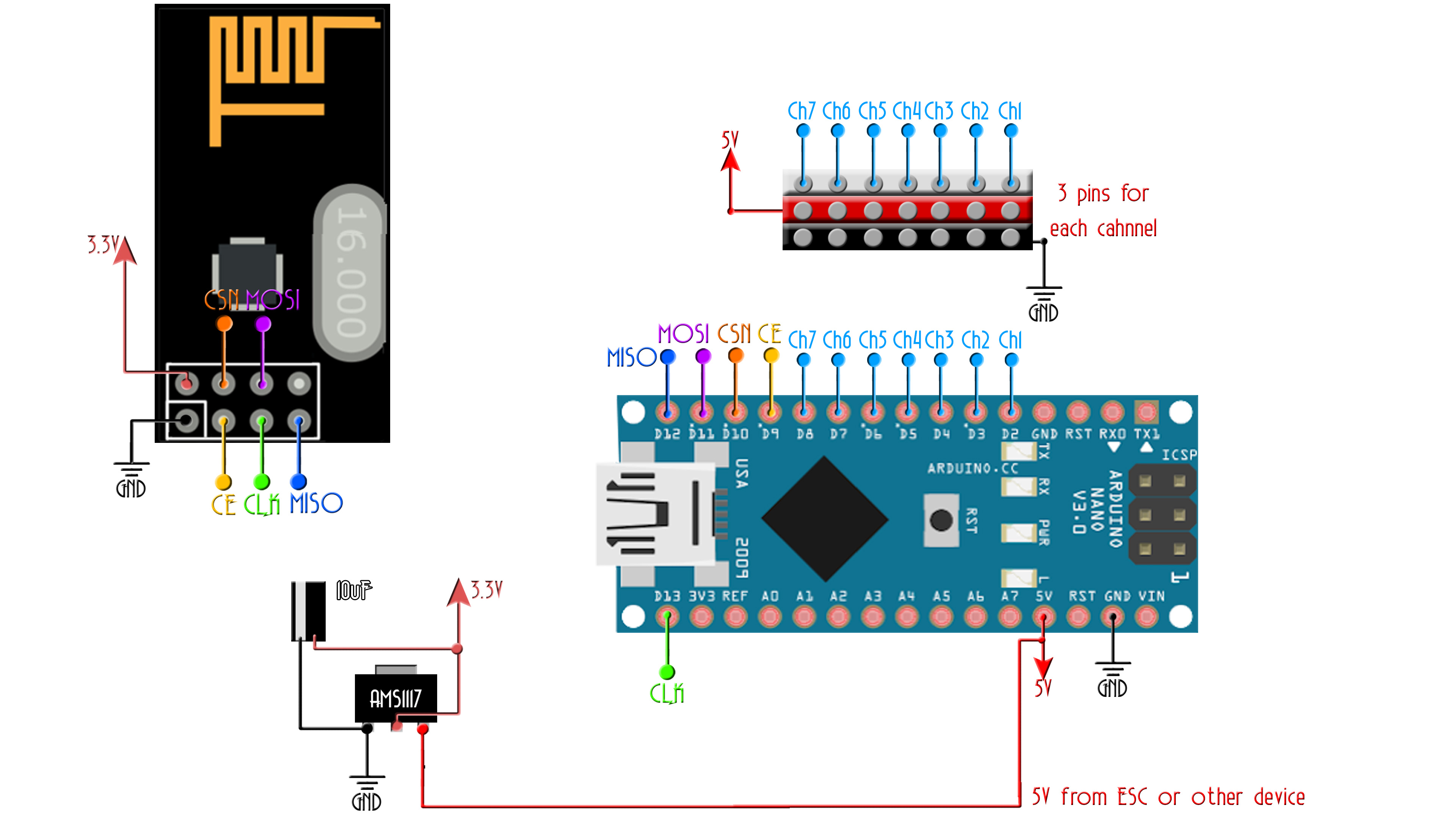
Module // Arduino UNO,NANO
GND -> GND
Vcc -> 3.3V
CE -> D9
CSN -> D10
CLK -> D13
MOSI -> D11
MISO -> D12
This code receive 6 channels and create a PWM output for each one on D2, D3, D4, D5, D6, D8
Please, like share and subscribe
*/
#include <SPI.h>
#include <nRF24L01.h> //Downlaod here: https://www.electronoobs.com/eng_arduino_NRF24_lib.php
#include <RF24.h>
#include <Servo.h> //To create PWM signals we need this lybrary
const uint64_t pipeIn = 0xE8E8F0F0E1LL; //Remember that this code is the same as in the transmitter
RF24 radio(9, 10); //CSN and CE pins
// The sizeof this struct should not exceed 32 bytes
struct Received_data {
byte ch1;
byte ch2;
byte ch3;
byte ch4;
byte ch5;
byte ch6;
byte ch7;
};
Received_data received_data;
Servo channel_1;
Servo channel_2;
Servo channel_3;
Servo channel_4;
Servo channel_5;
Servo channel_6;
Servo channel_7;
int ch1_value = 0;
int ch2_value = 0;
int ch3_value = 0;
int ch4_value = 0;
int ch5_value = 0;
int ch6_value = 0;
void reset_the_Data()
{
// 'safe' values to use when NO radio input is detected
received_data.ch1 = 0; //Throttle (channel 1) to 0
received_data.ch2 = 127;
received_data.ch3 = 127;
received_data.ch4 = 127;
received_data.ch5 = 0;
received_data.ch6 = 0;
}
/**************************************************/
void setup()
{
//Attach the servo signal on pins from D2 to D8
channel_1.attach(2);
channel_2.attach(3);
channel_3.attach(4);
channel_4.attach(5);
channel_5.attach(6);
channel_6.attach(7);
//We reset the received values
reset_the_Data();
//Once again, begin and radio configuration
radio.begin();
radio.setAutoAck(false);
radio.setDataRate(RF24_250KBPS);
radio.openReadingPipe(1,pipeIn);
//We start the radio comunication
radio.startListening();
}
/**************************************************/
unsigned long lastRecvTime = 0;
//We create the function that will read the data each certain time
void receive_the_data()
{
while ( radio.available() ) {
radio.read(&received_data, sizeof(Received_data));
lastRecvTime = millis(); //Here we receive the data
}
}
/**************************************************/
void loop()
{
//Receive the radio data
receive_the_data();
//////////This small if will reset the data if signal is lost for 1 sec.
/////////////////////////////////////////////////////////////////////////
unsigned long now = millis();
if ( now - lastRecvTime > 1000 ) {
// signal lost?
reset_the_Data();
//Go up and change the initial values if you want depending on
//your aplications. Put 0 for throttle in case of drones so it won't
//fly away
}
ch1_value = map(received_data.ch1,0,255,1000,2000);
ch2_value = map(received_data.ch2,0,255,1000,2000);
ch3_value = map(received_data.ch3,0,255,1000,2000);
ch4_value = map(received_data.ch4,0,255,1000,2000);
ch5_value = map(received_data.ch5,0,1,1000,2000);
ch6_value = map(received_data.ch6,0,1,1000,2000);
//Creathe the PWM signals
channel_1.writeMicroseconds(ch1_value);
channel_2.writeMicroseconds(ch2_value);
channel_3.writeMicroseconds(ch3_value);
channel_4.writeMicroseconds(ch4_value);
channel_5.writeMicroseconds(ch5_value);
channel_6.writeMicroseconds(ch6_value);
}//Loop end


