
This is the code for the Arduino based digital power supply project. Make sure you also install the needed library for the i2c LCD control. Download those from below. Install the library, compile and uplaod the code to the Arduino. Downlaod the zip file or copy+paste from below. Read all comments in the code!
/*
/* Digital power supply code by http://ELECTRONBOOBS.com
* Tutorial: http://ELECTRONBOOBS.com/eng_arduino_tut85.php
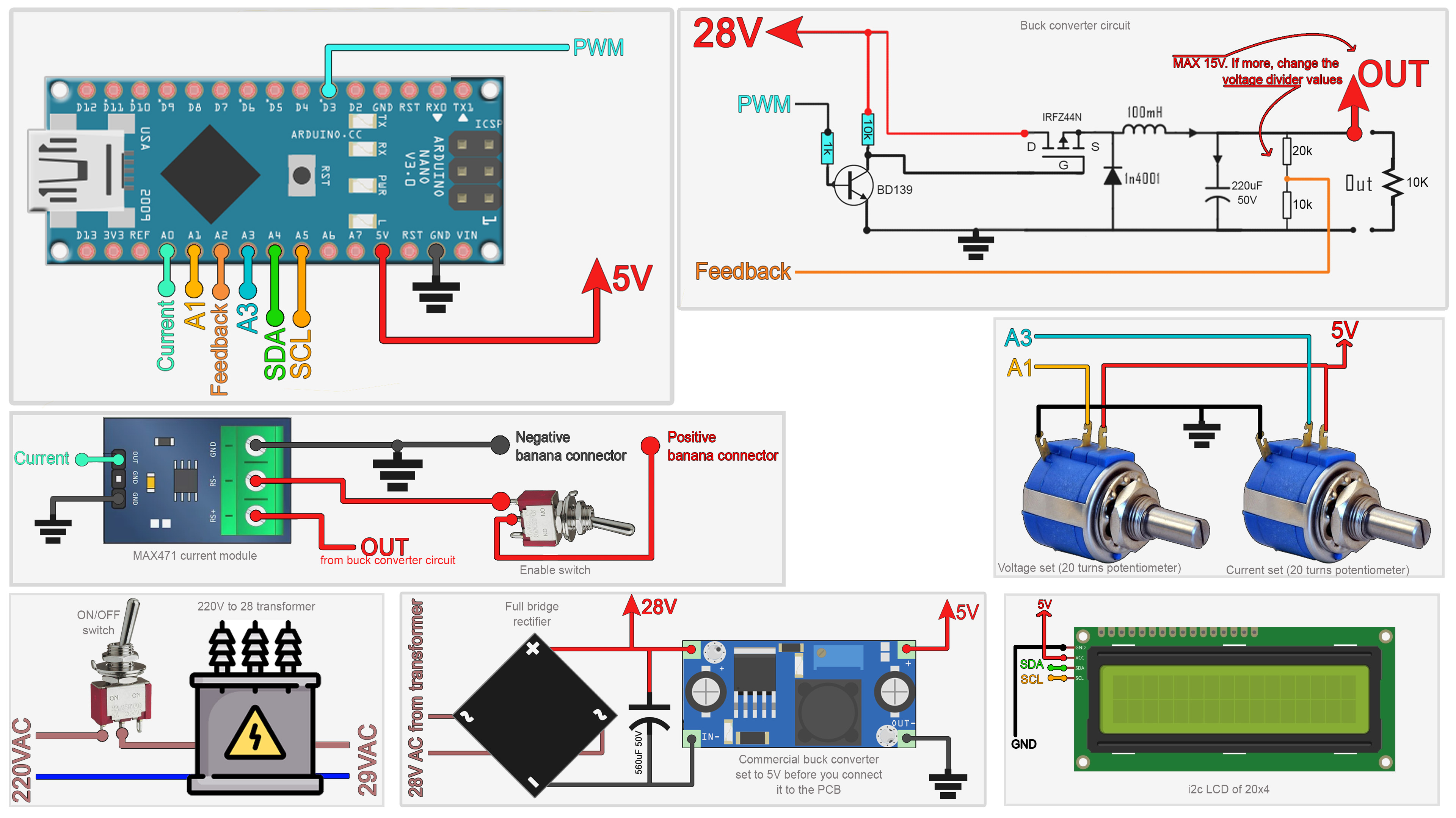
* Schematic: http://ELECTRONBOOBS.com/eng_arduino_tut85_sch_1.php
* Like share and subscibe: http://youtube.com/c/ELECTRONOOBS */
#include <Wire.h>
#include <LiquidCrystal_I2C.h> //Downlaod it here: http://www.electronoobs.com/eng_arduino_liq_crystal.php
LiquidCrystal_I2C lcd(0x27,20,4); //Soemtimes adres is 0x27 or 0x3f. Change it if it doesn't work
//Inputs/outputs
int voltage_in = A2;
int set_voltage_in = A1;
int set_current_in = A3;
int current_in = A0;
int PWM_PIN = 3;
//Editable variables
float real_curren_offset = -0.03;
int Delay= 1000;
float max_output_voltage= 15.0;
//Other Variables
int pwm_value = 1;
float set_voltage = 4.3;
float serial_lecture = 0;
float real_output = 0;
float real_output2 = 0;
float RawValue= 0;
float real_current = 0;
float real_current_ma = 0;
float set_volt = 0;
float set_curr= 0;
unsigned long previousMillis = 0;
unsigned long currentMillis = 0;
float map_divider = 0;
//THIS FUNCTION WILL MAP THE float VALUES IN THE GIVEN RANGE
float fmap(float x, float in_min, float in_max, float out_min, float out_max) {
return (x - in_min) * (out_max - out_min) / (in_max - in_min) + out_min;
}
void setup() {
lcd.init();
lcd.backlight();
pinMode(voltage_in,INPUT);
pinMode(set_voltage_in,INPUT);
pinMode(set_current_in,INPUT);
pinMode(current_in,INPUT);
pinMode(PWM_PIN,OUTPUT);
TCCR2B = TCCR2B & B11111000 | B00000001; // pin 3 PWM frequency of 31372.55 Hz
Serial.begin(9600);
currentMillis = millis();
map_divider = 1024.0/max_output_voltage; //I want maximum voltage of 15V in my case. SO 1024 digital read divided by 15 = 68.2
}
void loop() {
set_voltage = analogRead(set_voltage_in)/map_divider; //map_divider = 69.2 in my case Why 68.2? Well: I want maximum voltage of 15V. SO 1024 digital read divided by 15 = 68.2
set_curr = analogRead(set_current_in)/1.024; //Why divided by 1.024? Well: I want maximum current of 1000mA. SO 1024 digital read divided by 1000mA = 1.024
RawValue = analogRead(current_in); //Read the feedback for current from the MAX471 sensor
real_current = (RawValue * 5.0 )/ 1024.0; //Scale the ADC, we get current value in Amps
real_current = real_current - real_curren_offset; //Substract the current error. Make tests in order to find the real_curren_offset value, in my case an error of -0.03A
real_output= analogRead(voltage_in); //We read the feedback voltage (0 - 1024)
real_output2 = real_output/map_divider; //Divide by 69.2 and we get range to 15V
real_current_ma = real_current*1000; //We pass from A to mA
real_current_ma = constrain(real_current_ma,0,2000);
/////////////////////////////////////////////////////////////////////////////////////////////////////////////////////
//If the set current value is higher than the feedback current value, we make normal control of output voltage
if(real_current_ma < set_curr)
{
//Now, if set voltage is higher than real value from feedback, we decrease PWM width till we get same value
if(set_voltage > real_output2)
{
pwm_value = pwm_value - 1; //When we decrease PWM width, the volage gets higher at the output.
pwm_value = constrain(pwm_value, 0, 255);
}
//If set voltage is lower than real value from feedback, we increase PWM width till we get same value
if(set_voltage < real_output2)
{
pwm_value = pwm_value + 1; //When we increase PWM width, the volage gets lower at the output.
pwm_value = constrain(pwm_value, 0, 255);
}
}//end of real_current_ma < set_curr
/////////////////////////////////////////////////////////////////////////////////////////////////////////////////////
/////////////////////////////////////////////////////////////////////////////////////////////////////////////////////
/*if the set current value is lower than the feedback current value, that means we need to lower the voltage at the output
in order to amintain the same current value*/
if(real_current_ma > set_curr)
{
pwm_value = pwm_value + 1; //When we increase PWM width, the volage gets lower at the output.
pwm_value = constrain(pwm_value, 0, 255);
}
/////////////////////////////////////////////////////////////////////////////////////////////////////////////////////
/////////////////////////////////////////////////////////////////////////////////////////////////////////////////////
//We write PWM value on PWM pin out
analogWrite(PWM_PIN,pwm_value);
/////////////////////////////////////////////////////////////////////////////////////////////////////////////////////
//Each Delay value we print values on the LCD screen
currentMillis = millis();
if(currentMillis - previousMillis >= Delay){
previousMillis += Delay;
lcd.clear();
lcd.setCursor(0,0);
lcd.print(" VOLTAGE CURRENT ");
lcd.setCursor(0,1);
lcd.print(set_voltage,1);
lcd.print("V ");
lcd.print(set_curr,0);
lcd.print("mA");
lcd.setCursor(0,3);
lcd.print(real_output2,1);
lcd.print("V ");
lcd.print(real_current_ma,0);
//lcd.setCursor(19,1);
lcd.print("mA");
}//end of currentMillis - previousMillis >= Delay
}//end of void loop


