
See more on this other tutorial.The MPU-6050 is an inertial measurement unit (IMU) of six degrees of freedom (6DOF) manufactured by Invensense, which combines a 3-axis accelerometer and a 3-axis gyroscope. The communication can be done both by SPI and I2C bus, so it is easy to obtain the measured data. The supply voltage is low voltage between 2.4 to 3.6V. It has digital analog converters (ADC) of 16 bits. The range of the accelerometer can be adjusted to ± 2g, ± 4g, ± 8g, and ± 16g, that of the gyroscope to ± 250, ± 500, ± 1000, and ± 2000 ° / sec.
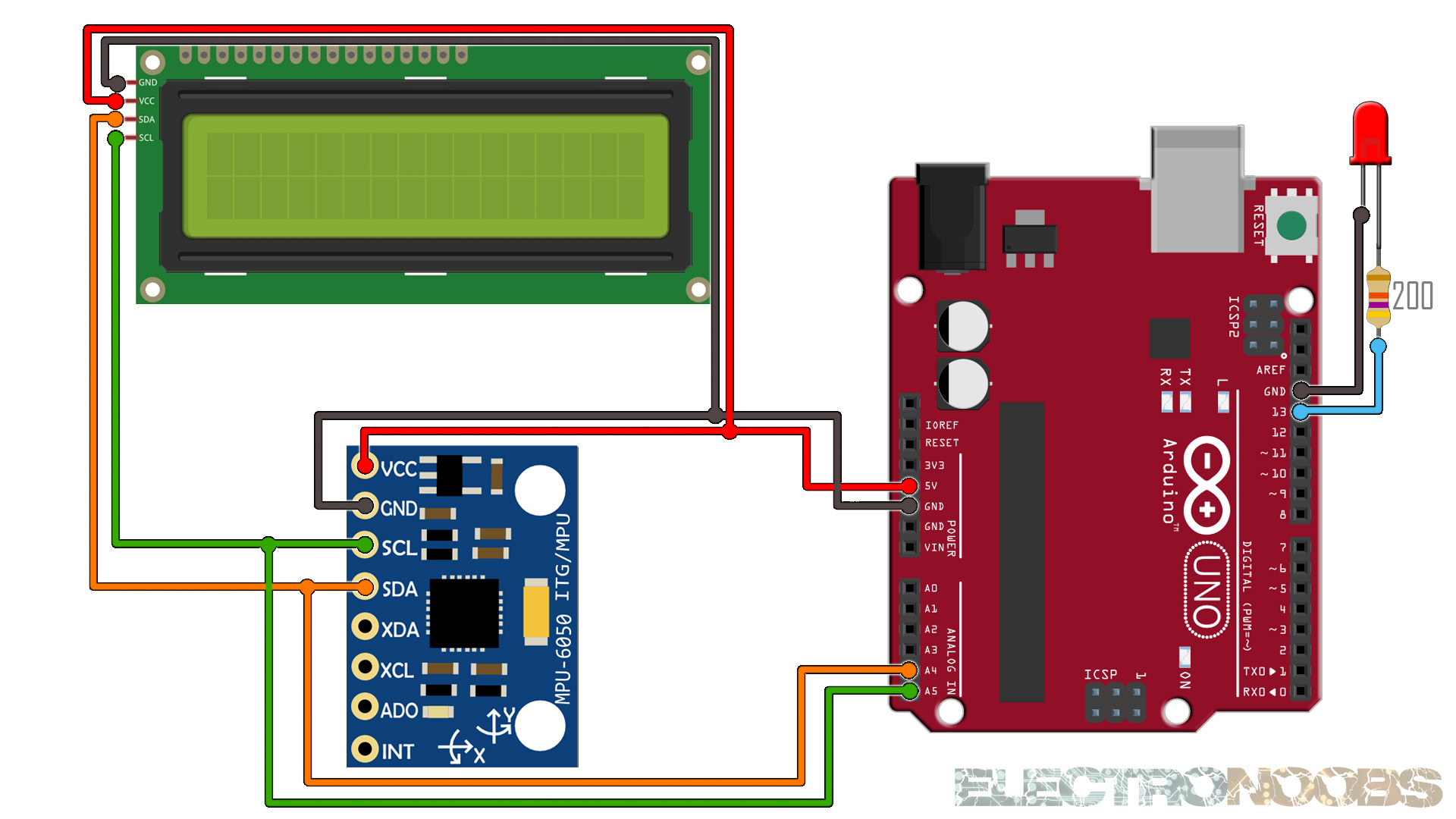
The connections are pretty easy, see the image below with the breadboard circuit schematic. The MPU6050 uses i2c communication so connect SCL to A5 of the Arduino and SDA to A4 of the Arduino. Do the same for the i2c LCD incase that you want to print the results on the LCD. The LED is extra.
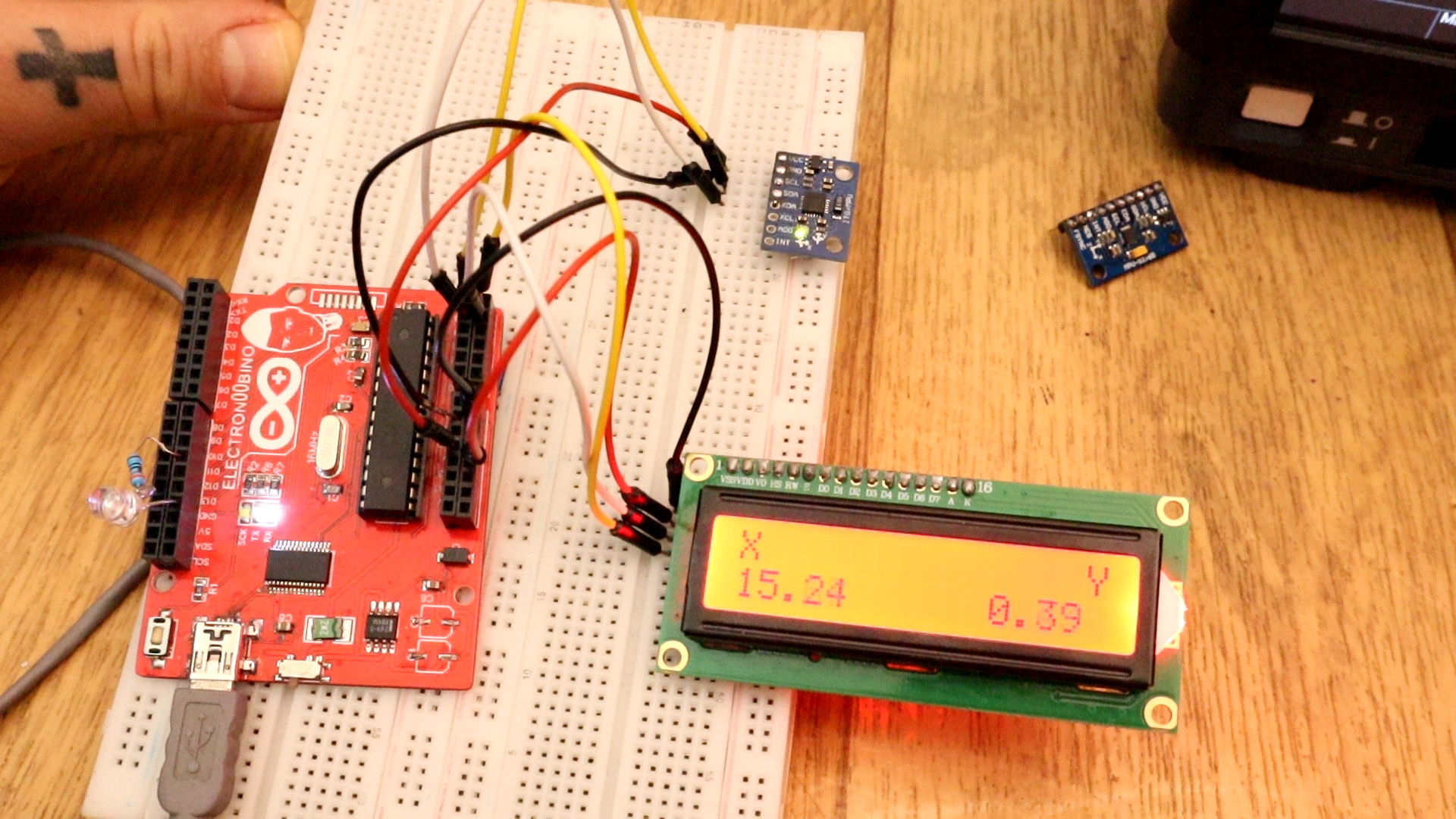
We use i2c to get the raw data of gyro and acc. With those using Euler formula we oobtain the angle and then we apply a small filter. We print the data to the Serial monitor or to the LCD if we use the other code. Download the code, compile and upload.
/* http://www.youtube.com/c/electronoobs/eng_arduino_tut76.php
 * This is an example where we configure te data of the MPU6050
 * and read the Acceleration data and print it to the serial monitor
 * Arduino pin    |   MPU6050
 * 5V             |   Vcc
 * GND            |   GND
 * A4             |   SDA
 * A5             |   SCL
 */
//Gyro Variables
float elapsedTime, time, timePrev;        //Variables for time control
int gyro_error=0;                         //We use this variable to only calculate once the gyro data error
float Gyr_rawX, Gyr_rawY, Gyr_rawZ;     //Here we store the raw data read
float Gyro_angle_x, Gyro_angle_y;         //Here we store the angle value obtained with Gyro data
float Gyro_raw_error_x, Gyro_raw_error_y; //Here we store the initial gyro data error

//Acc Variables
int acc_error=0;                         //We use this variable to only calculate once the Acc data error
float rad_to_deg = 180/3.141592654;      //This value is for pasing from radians to degrees values
float Acc_rawX, Acc_rawY, Acc_rawZ;    //Here we store the raw data read
float Acc_angle_x, Acc_angle_y;          //Here we store the angle value obtained with Acc data
float Acc_angle_error_x, Acc_angle_error_y; //Here we store the initial Acc data error

float Total_angle_x, Total_angle_y;


void setup() {
  Wire.begin();                           //begin the wire comunication
  Wire.beginTransmission(0x68);           //begin, Send the slave adress (in this case 68)
  Wire.write(0x6B);                       //make the reset (place a 0 into the 6B register)
  Wire.write(0x00);
  Wire.endTransmission(true);             //end the transmission
  //Gyro config
  Wire.beginTransmission(0x68);           //begin, Send the slave adress (in this case 68)
  Wire.write(0x1B);                       //We want to write to the GYRO_CONFIG register (1B hex)
  Wire.write(0x10);                       //Set the register bits as 00010000 (1000dps full scale)
  Wire.endTransmission(true);             //End the transmission with the gyro
  //Acc config
  Wire.beginTransmission(0x68);           //Start communication with the address found during search.
  Wire.write(0x1C);                       //We want to write to the ACCEL_CONFIG register
  Wire.write(0x10);                       //Set the register bits as 00010000 (+/- 8g full scale range)
  Wire.endTransmission(true);

  Serial.begin(9600);                     //Remember to set this same baud rate to the serial monitor
  time = millis();                        //Start counting time in milliseconds


/*Here we calculate the acc data error before we start the loop
 * I make the mean of 200 values, that should be enough*/
  if(acc_error==0)
  {
    for(int a=0; a<200; a++)
    {
      Wire.beginTransmission(0x68);
      Wire.write(0x3B);                       //Ask for the 0x3B register- correspond to AcX
      Wire.endTransmission(false);
      Wire.requestFrom(0x68,6,true);

      Acc_rawX=(Wire.read()<<8|Wire.read())/4096.0 ; //each value needs two registres
      Acc_rawY=(Wire.read()<<8|Wire.read())/4096.0 ;
      Acc_rawZ=(Wire.read()<<8|Wire.read())/4096.0 ;


      /*---X---*/
      Acc_angle_error_x = Acc_angle_error_x + ((atan((Acc_rawY)/sqrt(pow((Acc_rawX),2) + pow((Acc_rawZ),2)))*rad_to_deg));
      /*---Y---*/
      Acc_angle_error_y = Acc_angle_error_y + ((atan(-1*(Acc_rawX)/sqrt(pow((Acc_rawY),2) + pow((Acc_rawZ),2)))*rad_to_deg));

      if(a==199)
      {
        Acc_angle_error_x = Acc_angle_error_x/200;
        Acc_angle_error_y = Acc_angle_error_y/200;
        acc_error=1;
      }
    }
  }//end of acc error calculation


/*Here we calculate the gyro data error before we start the loop
 * I make the mean of 200 values, that should be enough*/
  if(gyro_error==0)
  {
    for(int i=0; i<200; i++)
    {
      Wire.beginTransmission(0x68);            //begin, Send the slave adress (in this case 68)
      Wire.write(0x43);                        //First adress of the Gyro data
      Wire.endTransmission(false);
      Wire.requestFrom(0x68,4,true);           //We ask for just 4 registers

      Gyr_rawX=Wire.read()<<8|Wire.read();     //Once again we shif and sum
      Gyr_rawY=Wire.read()<<8|Wire.read();

      /*---X---*/
      Gyro_raw_error_x = Gyro_raw_error_x + (Gyr_rawX/32.8);
      /*---Y---*/
      Gyro_raw_error_y = Gyro_raw_error_y + (Gyr_rawY/32.8);
      if(i==199)
      {
        Gyro_raw_error_x = Gyro_raw_error_x/200;
        Gyro_raw_error_y = Gyro_raw_error_y/200;
        gyro_error=1;
      }
    }
  }//end of gyro error calculation
}//end of setup void


void loop() {
  timePrev = time;                        // the previous time is stored before the actual time read
  time = millis();                        // actual time read
  elapsedTime = (time - timePrev) / 1000; //divide by 1000 in order to obtain seconds

  //////////////////////////////////////Gyro read/////////////////////////////////////

    Wire.beginTransmission(0x68);            //begin, Send the slave adress (in this case 68)
    Wire.write(0x43);                        //First adress of the Gyro data
    Wire.endTransmission(false);
    Wire.requestFrom(0x68,4,true);           //We ask for just 4 registers

    Gyr_rawX=Wire.read()<<8|Wire.read();     //Once again we shif and sum
    Gyr_rawY=Wire.read()<<8|Wire.read();
    /*Now in order to obtain the gyro data in degrees/seconds we have to divide first
    the raw value by 32.8 because that's the value that the datasheet gives us for a 1000dps range*/
    /*---X---*/
    Gyr_rawX = (Gyr_rawX/32.8) - Gyro_raw_error_x;
    /*---Y---*/
    Gyr_rawY = (Gyr_rawY/32.8) - Gyro_raw_error_y;

    /*Now we integrate the raw value in degrees per seconds in order to obtain the angle
    * If you multiply degrees/seconds by seconds you obtain degrees */
    /*---X---*/
    Gyro_angle_x = Gyr_rawX*elapsedTime;
    /*---X---*/
    Gyro_angle_y = Gyr_rawY*elapsedTime;


  //////////////////////////////////////Acc read/////////////////////////////////////

  Wire.beginTransmission(0x68);     //begin, Send the slave adress (in this case 68)
  Wire.write(0x3B);                 //Ask for the 0x3B register- correspond to AcX
  Wire.endTransmission(false);      //keep the transmission and next
  Wire.requestFrom(0x68,6,true);    //We ask for next 6 registers starting withj the 3B
  /*We have asked for the 0x3B register. The IMU will send a brust of register.
  * The amount of register to read is specify in the requestFrom function.
  * In this case we request 6 registers. Each value of acceleration is made out of
  * two 8bits registers, low values and high values. For that we request the 6 of them
  * and just make then sum of each pair. For that we shift to the left the high values
  * register (<<) and make an or (|) operation to add the low values.
  If we read the datasheet, for a range of+-8g, we have to divide the raw values by 4096*/
  Acc_rawX=(Wire.read()<<8|Wire.read())/4096.0 ; //each value needs two registres
  Acc_rawY=(Wire.read()<<8|Wire.read())/4096.0 ;
  Acc_rawZ=(Wire.read()<<8|Wire.read())/4096.0 ;
 /*Now in order to obtain the Acc angles we use euler formula with acceleration values
 after that we substract the error value found before*/
 /*---X---*/
 Acc_angle_x = (atan((Acc_rawY)/sqrt(pow((Acc_rawX),2) + pow((Acc_rawZ),2)))*rad_to_deg) - Acc_angle_error_x;
 /*---Y---*/
 Acc_angle_y = (atan(-1*(Acc_rawX)/sqrt(pow((Acc_rawY),2) + pow((Acc_rawZ),2)))*rad_to_deg) - Acc_angle_error_y;


 //////////////////////////////////////Total angle and filter/////////////////////////////////////
 /*---X axis angle---*/
 Total_angle_x = 0.98 *(Total_angle_x + Gyro_angle_x) + 0.02*Acc_angle_x;
 /*---Y axis angle---*/
 Total_angle_y = 0.98 *(Total_angle_y + Gyro_angle_y) + 0.02*Acc_angle_y;


 /*Uncoment the rest of the serial prines
 * I only print the Y angle value for this test */
 Serial.print("Xº: ");
 Serial.print(Total_angle_x);
 Serial.print("   |   ");
 Serial.print("Yº: ");
 Serial.print(Total_angle_y);
 Serial.println(" ");
 delay(200);


}
Upload the code and make the connections. Then open the serial monitor at 9600 bauds and you will have the angles printed to the serial monitor. Or go below and download the code with the i2c LCD.
/* http://www.youtube.com/c/electronoobs/eng_arduino_tut76.php
 * This is an example where we configure te data of the MPU6050
 * and read the Acceleration data and print it to the serial monitor
 * Arduino pin    |   MPU6050
 * 5V             |   Vcc
 * GND            |   GND
 * A4             |   SDA
 * A5             |   SCL
 */

//Includes
#include <Wire.h>
#include <LiquidCrystal_I2C.h>

// Set the LCD address to 0x27 or 0x3f for a 16 chars and 2 line display
LiquidCrystal_I2C lcd(0x27, 20, 4);


//Gyro Variables
float elapsedTime, time, timePrev;        //Variables for time control
int gyro_error=0;                         //We use this variable to only calculate once the gyro data error
float Gyr_rawX, Gyr_rawY, Gyr_rawZ;     //Here we store the raw data read
float Gyro_angle_x, Gyro_angle_y;         //Here we store the angle value obtained with Gyro data
float Gyro_raw_error_x, Gyro_raw_error_y; //Here we store the initial gyro data error

//Acc Variables
int acc_error=0;                         //We use this variable to only calculate once the Acc data error
float rad_to_deg = 180/3.141592654;      //This value is for pasing from radians to degrees values
float Acc_rawX, Acc_rawY, Acc_rawZ;    //Here we store the raw data read
float Acc_angle_x, Acc_angle_y;          //Here we store the angle value obtained with Acc data
float Acc_angle_error_x, Acc_angle_error_y; //Here we store the initial Acc data error

float Total_angle_x, Total_angle_y;


void setup() {
  lcd.init();
  lcd.backlight();

  Wire.begin();                           //begin the wire comunication

  Wire.beginTransmission(0x68);           //begin, Send the slave adress (in this case 68)
  Wire.write(0x6B);                       //make the reset (place a 0 into the 6B register)
  Wire.write(0x00);
  Wire.endTransmission(true);             //end the transmission
  //Gyro config
  Wire.beginTransmission(0x68);           //begin, Send the slave adress (in this case 68)
  Wire.write(0x1B);                       //We want to write to the GYRO_CONFIG register (1B hex)
  Wire.write(0x10);                       //Set the register bits as 00010000 (1000dps full scale)
  Wire.endTransmission(true);             //End the transmission with the gyro
  //Acc config
  Wire.beginTransmission(0x68);           //Start communication with the address found during search.
  Wire.write(0x1C);                       //We want to write to the ACCEL_CONFIG register
  Wire.write(0x10);                       //Set the register bits as 00010000 (+/- 8g full scale range)
  Wire.endTransmission(true);

  Serial.begin(9600);                     //Remember to set this same baud rate to the serial monitor
  time = millis();                        //Start counting time in milliseconds


/*Here we calculate the acc data error before we start the loop
 * I make the mean of 200 values, that should be enough*/
  if(acc_error==0)
  {
    for(int a=0; a<200; a++)
    {
      Wire.beginTransmission(0x68);
      Wire.write(0x3B);                       //Ask for the 0x3B register- correspond to AcX
      Wire.endTransmission(false);
      Wire.requestFrom(0x68,6,true);

      Acc_rawX=(Wire.read()<<8|Wire.read())/4096.0 ; //each value needs two registres
      Acc_rawY=(Wire.read()<<8|Wire.read())/4096.0 ;
      Acc_rawZ=(Wire.read()<<8|Wire.read())/4096.0 ;


      /*---X---*/
      Acc_angle_error_x = Acc_angle_error_x + ((atan((Acc_rawY)/sqrt(pow((Acc_rawX),2) + pow((Acc_rawZ),2)))*rad_to_deg));
      /*---Y---*/
      Acc_angle_error_y = Acc_angle_error_y + ((atan(-1*(Acc_rawX)/sqrt(pow((Acc_rawY),2) + pow((Acc_rawZ),2)))*rad_to_deg));

      if(a==199)
      {
        Acc_angle_error_x = Acc_angle_error_x/200;
        Acc_angle_error_y = Acc_angle_error_y/200;
        acc_error=1;
      }
    }
  }//end of acc error calculation


/*Here we calculate the gyro data error before we start the loop
 * I make the mean of 200 values, that should be enough*/
  if(gyro_error==0)
  {
    for(int i=0; i<200; i++)
    {
      Wire.beginTransmission(0x68);            //begin, Send the slave adress (in this case 68)
      Wire.write(0x43);                        //First adress of the Gyro data
      Wire.endTransmission(false);
      Wire.requestFrom(0x68,4,true);           //We ask for just 4 registers

      Gyr_rawX=Wire.read()<<8|Wire.read();     //Once again we shif and sum
      Gyr_rawY=Wire.read()<<8|Wire.read();

      /*---X---*/
      Gyro_raw_error_x = Gyro_raw_error_x + (Gyr_rawX/32.8);
      /*---Y---*/
      Gyro_raw_error_y = Gyro_raw_error_y + (Gyr_rawY/32.8);
      if(i==199)
      {
        Gyro_raw_error_x = Gyro_raw_error_x/200;
        Gyro_raw_error_y = Gyro_raw_error_y/200;
        gyro_error=1;
      }
    }
  }//end of gyro error calculation
}//end of setup void


void loop() {
  timePrev = time;                        // the previous time is stored before the actual time read
  time = millis();                        // actual time read
  elapsedTime = (time - timePrev) / 1000; //divide by 1000 in order to obtain seconds

  //////////////////////////////////////Gyro read/////////////////////////////////////

    Wire.beginTransmission(0x68);            //begin, Send the slave adress (in this case 68)
    Wire.write(0x43);                        //First adress of the Gyro data
    Wire.endTransmission(false);
    Wire.requestFrom(0x68,4,true);           //We ask for just 4 registers

    Gyr_rawX=Wire.read()<<8|Wire.read();     //Once again we shif and sum
    Gyr_rawY=Wire.read()<<8|Wire.read();
    /*Now in order to obtain the gyro data in degrees/seconds we have to divide first
    the raw value by 32.8 because that's the value that the datasheet gives us for a 1000dps range*/
    /*---X---*/
    Gyr_rawX = (Gyr_rawX/32.8) - Gyro_raw_error_x;
    /*---Y---*/
    Gyr_rawY = (Gyr_rawY/32.8) - Gyro_raw_error_y;

    /*Now we integrate the raw value in degrees per seconds in order to obtain the angle
    * If you multiply degrees/seconds by seconds you obtain degrees */
    /*---X---*/
    Gyro_angle_x = Gyr_rawX*elapsedTime;
    /*---X---*/
    Gyro_angle_y = Gyr_rawY*elapsedTime;


  //////////////////////////////////////Acc read/////////////////////////////////////

  Wire.beginTransmission(0x68);     //begin, Send the slave adress (in this case 68)
  Wire.write(0x3B);                 //Ask for the 0x3B register- correspond to AcX
  Wire.endTransmission(false);      //keep the transmission and next
  Wire.requestFrom(0x68,6,true);    //We ask for next 6 registers starting withj the 3B
  /*We have asked for the 0x3B register. The IMU will send a brust of register.
  * The amount of register to read is specify in the requestFrom function.
  * In this case we request 6 registers. Each value of acceleration is made out of
  * two 8bits registers, low values and high values. For that we request the 6 of them
  * and just make then sum of each pair. For that we shift to the left the high values
  * register (<<) and make an or (|) operation to add the low values.
  If we read the datasheet, for a range of+-8g, we have to divide the raw values by 4096*/
  Acc_rawX=(Wire.read()<<8|Wire.read())/4096.0 ; //each value needs two registres
  Acc_rawY=(Wire.read()<<8|Wire.read())/4096.0 ;
  Acc_rawZ=(Wire.read()<<8|Wire.read())/4096.0 ;
 /*Now in order to obtain the Acc angles we use euler formula with acceleration values
 after that we substract the error value found before*/
 /*---X---*/
 Acc_angle_x = (atan((Acc_rawY)/sqrt(pow((Acc_rawX),2) + pow((Acc_rawZ),2)))*rad_to_deg) - Acc_angle_error_x;
 /*---Y---*/
 Acc_angle_y = (atan(-1*(Acc_rawX)/sqrt(pow((Acc_rawY),2) + pow((Acc_rawZ),2)))*rad_to_deg) - Acc_angle_error_y;


 //////////////////////////////////////Total angle and filter/////////////////////////////////////
 /*---X axis angle---*/
 Total_angle_x = 0.98 *(Total_angle_x + Gyro_angle_x) + 0.02*Acc_angle_x;
 /*---Y axis angle---*/
 Total_angle_y = 0.98 *(Total_angle_y + Gyro_angle_y) + 0.02*Acc_angle_y;


 /*Uncoment the rest of the serial prines
 * I only print the Y angle value for this test */
 Serial.print("Xº: ");
 Serial.print(Total_angle_x);
 Serial.print("   |   ");
 Serial.print("Yº: ");
 Serial.print(Total_angle_y);
 Serial.println(" ");
 lcd.clear();
 lcd.setCursor(0,0);
 lcd.print("X              Y");
 lcd.setCursor(0,1);
 lcd.print(Total_angle_x);
 lcd.setCursor(11,1);
 lcd.print(Total_angle_y);
 delay(200);


}
Upload the code and make the connections. Then open the serial monitor at 9600 bauds or just see the results on the LCD screen. We only getb the X and Y angles which are roll and pitch. The YAW, or Z angle is not calculated.
/* http://www.youtube.com/c/electronoobs/eng_arduino_tut76.php *
 * This is an example where we configure te data of the MPU6050
 * and read the Acceleration data and detect movement
 * Arduino pin    |   MPU6050
 * 5V             |   Vcc
 * GND            |   GND
 * A4             |   SDA
 * A5             |   SCL
 */

int LED = 13;

//Gyro Variables
float elapsedTime, time, timePrev;        //Variables for time control
int gyro_error=0;                         //We use this variable to only calculate once the gyro data error
float Gyr_rawX, Gyr_rawY, Gyr_rawZ;     //Here we store the raw data read
float Gyro_angle_x, Gyro_angle_y;         //Here we store the angle value obtained with Gyro data
float Gyro_raw_error_x, Gyro_raw_error_y; //Here we store the initial gyro data error

//Acc Variables
int acc_error=0;                         //We use this variable to only calculate once the Acc data error
float rad_to_deg = 180/3.141592654;      //This value is for pasing from radians to degrees values
float Acc_rawX, Acc_rawY, Acc_rawZ;    //Here we store the raw data read
float Acc_angle_x, Acc_angle_y;          //Here we store the angle value obtained with Acc data
float Acc_angle_error_x, Acc_angle_error_y; //Here we store the initial Acc data error
float Total_angle_x, Total_angle_y;
float prev_acc_x = 1000;

void setup() {

  pinMode(LED,OUTPUT);
  digitalWrite(LED,LOW);

  Wire.begin();                           //begin the wire comunication
  Wire.beginTransmission(0x68);           //begin, Send the slave adress (in this case 68)
  Wire.write(0x6B);                       //make the reset (place a 0 into the 6B register)
  Wire.write(0x00);
  Wire.endTransmission(true);             //end the transmission
  //Gyro config
  Wire.beginTransmission(0x68);           //begin, Send the slave adress (in this case 68)
  Wire.write(0x1B);                       //We want to write to the GYRO_CONFIG register (1B hex)
  Wire.write(0x10);                       //Set the register bits as 00010000 (1000dps full scale)
  Wire.endTransmission(true);             //End the transmission with the gyro
  //Acc config
  Wire.beginTransmission(0x68);           //Start communication with the address found during search.
  Wire.write(0x1C);                       //We want to write to the ACCEL_CONFIG register
  Wire.write(0x10);                       //Set the register bits as 00010000 (+/- 8g full scale range)
  Wire.endTransmission(true);

  Serial.begin(9600);                     //Remember to set this same baud rate to the serial monitor
  time = millis();                        //Start counting time in milliseconds


/*Here we calculate the acc data error before we start the loop
 * I make the mean of 200 values, that should be enough*/
  if(acc_error==0)
  {
    for(int a=0; a<200; a++)
    {
      Wire.beginTransmission(0x68);
      Wire.write(0x3B);                       //Ask for the 0x3B register- correspond to AcX
      Wire.endTransmission(false);
      Wire.requestFrom(0x68,6,true);

      Acc_rawX=(Wire.read()<<8|Wire.read())/4096.0 ; //each value needs two registres
      Acc_rawY=(Wire.read()<<8|Wire.read())/4096.0 ;
      Acc_rawZ=(Wire.read()<<8|Wire.read())/4096.0 ;


      /*---X---*/
      Acc_angle_error_x = Acc_angle_error_x + ((atan((Acc_rawY)/sqrt(pow((Acc_rawX),2) + pow((Acc_rawZ),2)))*rad_to_deg));
      /*---Y---*/
      Acc_angle_error_y = Acc_angle_error_y + ((atan(-1*(Acc_rawX)/sqrt(pow((Acc_rawY),2) + pow((Acc_rawZ),2)))*rad_to_deg));

      if(a==199)
      {
        Acc_angle_error_x = Acc_angle_error_x/200;
        Acc_angle_error_y = Acc_angle_error_y/200;
        acc_error=1;
      }
    }
  }//end of acc error calculation


/*Here we calculate the gyro data error before we start the loop
 * I make the mean of 200 values, that should be enough*/
  if(gyro_error==0)
  {
    for(int i=0; i<200; i++)
    {
      Wire.beginTransmission(0x68);            //begin, Send the slave adress (in this case 68)
      Wire.write(0x43);                        //First adress of the Gyro data
      Wire.endTransmission(false);
      Wire.requestFrom(0x68,4,true);           //We ask for just 4 registers

      Gyr_rawX=Wire.read()<<8|Wire.read();     //Once again we shif and sum
      Gyr_rawY=Wire.read()<<8|Wire.read();

      /*---X---*/
      Gyro_raw_error_x = Gyro_raw_error_x + (Gyr_rawX/32.8);
      /*---Y---*/
      Gyro_raw_error_y = Gyro_raw_error_y + (Gyr_rawY/32.8);
      if(i==199)
      {
        Gyro_raw_error_x = Gyro_raw_error_x/200;
        Gyro_raw_error_y = Gyro_raw_error_y/200;
        gyro_error=1;
      }
    }
  }//end of gyro error calculation
}//end of setup void


void loop() {
  //////////////////////////////////////Acc read/////////////////////////////////////

  Wire.beginTransmission(0x68);     //begin, Send the slave adress (in this case 68)
  Wire.write(0x3B);                 //Ask for the 0x3B register- correspond to AcX
  Wire.endTransmission(false);      //keep the transmission and next
  Wire.requestFrom(0x68,6,true);    //We ask for next 6 registers starting withj the 3B
  /*We have asked for the 0x3B register. The IMU will send a brust of register.
  * The amount of register to read is specify in the requestFrom function.
  * In this case we request 6 registers. Each value of acceleration is made out of
  * two 8bits registers, low values and high values. For that we request the 6 of them
  * and just make then sum of each pair. For that we shift to the left the high values
  * register (<<) and make an or (|) operation to add the low values.
  If we read the datasheet, for a range of+-8g, we have to divide the raw values by 4096*/
  Acc_rawX=(Wire.read()<<8|Wire.read())/4096.0 ; //each value needs two registres
  Acc_rawY=(Wire.read()<<8|Wire.read())/4096.0 ;
  Acc_rawZ=(Wire.read()<<8|Wire.read())/4096.0 ;

  //if the actual acc is 10 times bigger than the previous one, we
  //detect movement...
  if(Acc_rawX > abs((10*prev_acc_x)))
  {
    digitalWrite(LED,HIGH);
    Serial.println("Module moved");
    Serial.print("X acc = "); Serial.println(Acc_rawX);
    delay(3000);
    prev_acc_x = Acc_rawX;
  }

  else{
  digitalWrite(LED,LOW);
  prev_acc_x = Acc_rawX;

  }


}


