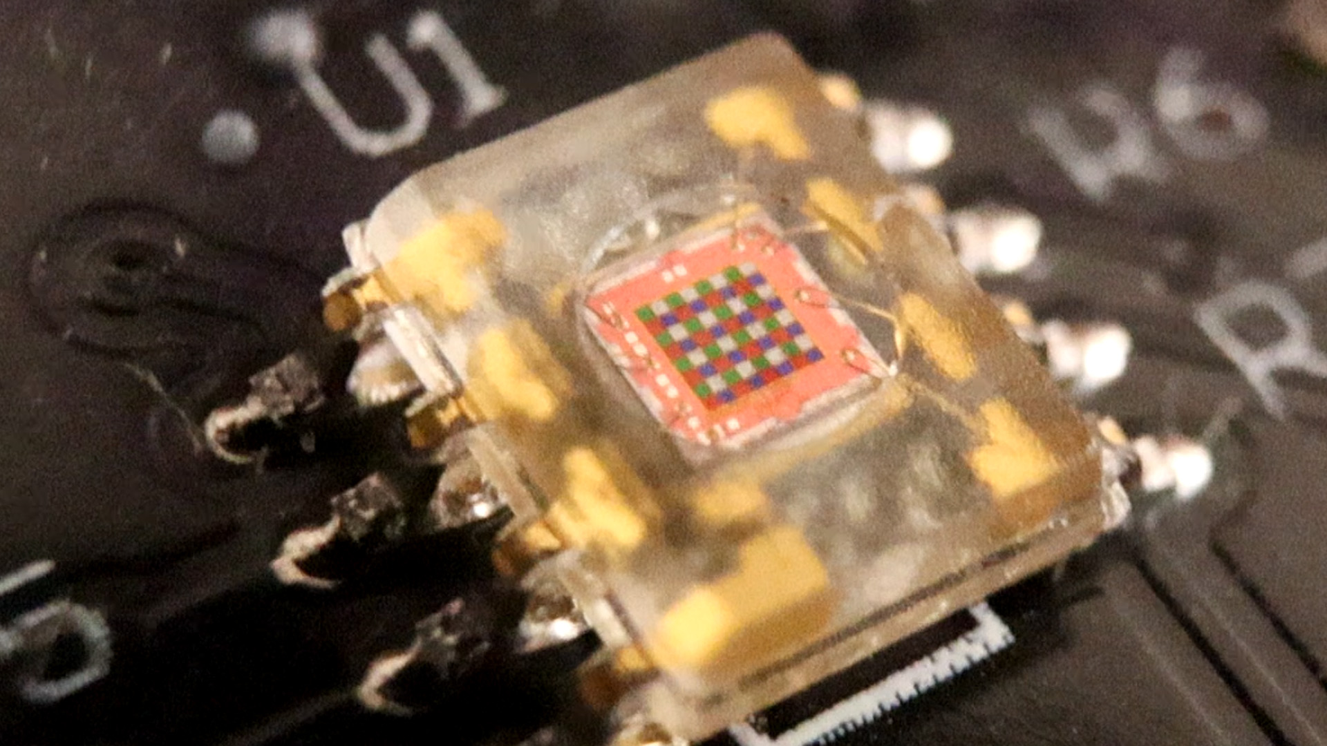

Basic example. See how to detect colors with this TCS3200 chip with photodiodes filters for red green and blue. We will detect the frequency response of each color using the Arduino. The TCS230 senses color light with the help of an 8 x 8 array of photodiodes. Then using a Current-to-Frequency Converter the readings from the photodiodes are converted into a square wave with a frequency directly proportional to the light intensity. Finally, using the Arduino Board we can read the square wave output and get the results for the color.

The sensor has two more control pins, S0 and S1 which are used for scaling the output frequency. The frequency can be scaled to three different preset values of 100 %, 20 % or 2%. This frequency-scaling function allows the output of the sensor to be optimized for various frequency counters or microcontrollers. Below you have the schematic used with this sensor. Make the connections and then uplaod the code.

First we need to define the pins to which the sensor is connected and define a variable for reading the frequency. In the setup section we need to define the four control pins as outputs and the sensor output as an Arduino input. Here we also need to set the frequency-scaling, for this example I will set it to 20%, and start the serial communication for displaying the results in the Serial Monitor.
In the loop section, we will start with reading the red filtered photodiodes. For that purpose we will set the two control pins S2 and S3 to low logic level. Then using the “pulseIn()” function we will read the output frequency and put it into the variable “frequency”. Using the Serial.print() function we will print the result on the serial monitor. The same procedure goes for the two other colors, we just need to adjust the control pins for the appropriate color.
//Tutorial: https://www.electronoobs.com/eng_arduino_tut70.php
// TCS230 or TCS3200 pins wiring to Arduino
#define S1 4
#define S0 5
#define S3 6
#define S2 7
#define sensorOut 8

// Stores frequency read by the photodiodes
int redFrequency = 0;
int greenFrequency = 0;
int blueFrequency = 0;

void setup() {
  // Setting the outputs
  pinMode(S0, OUTPUT);
  pinMode(S1, OUTPUT);
  pinMode(S2, OUTPUT);
  pinMode(S3, OUTPUT);

  // Setting the sensorOut as an input
  pinMode(sensorOut, INPUT);
  // Setting frequency scaling to 20%
  digitalWrite(S0,HIGH);
  digitalWrite(S1,LOW);
   // Begins serial communication
  Serial.begin(9600);
}
void loop() {
  // Setting RED (R) filtered photodiodes to be read
  digitalWrite(S2,LOW);
  digitalWrite(S3,LOW);

  // Reading the output frequency
  redFrequency = pulseIn(sensorOut, LOW);

   // Printing the RED (R) value
  Serial.print("R = ");
  Serial.print(redFrequency);
  delay(100);

  // Setting GREEN (G) filtered photodiodes to be read
  digitalWrite(S2,HIGH);
  digitalWrite(S3,HIGH);

  // Reading the output frequency
  greenFrequency = pulseIn(sensorOut, LOW);

  // Printing the GREEN (G) value
  Serial.print(" G = ");
  Serial.print(greenFrequency);
  delay(100);

  // Setting BLUE (B) filtered photodiodes to be read
  digitalWrite(S2,LOW);
  digitalWrite(S3,HIGH);

  // Reading the output frequency
  blueFrequency = pulseIn(sensorOut, LOW);

  // Printing the BLUE (B) value
  Serial.print(" B = ");
  Serial.println(blueFrequency);
  delay(100);
}
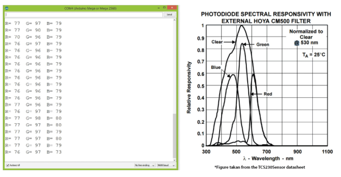
Now if we run the Serial Monitor we will start getting some values. These values depend on the selected frequency-scaling, as well as from the surrounding lighting.

For this part make sure you also download the i2c library for the LCD screen. Also make the connections SDA and SCL to the Arduino so we could print the values to the screen.
//Tutorial: https://www.electronoobs.com/eng_arduino_tut70.php
#include <Wire.h>
#include <LiquidCrystal_I2C.h>
// TCS230 or TCS3200 pins wiring to Arduino
#define S1 4
#define S0 5
#define S3 6
#define S2 7
#define sensorOut 8

// Set the LCD address to 0x27 or 0x3f for a 16 chars and 2 line display
LiquidCrystal_I2C lcd(0x27, 20, 4);

// Stores frequency read by the photodiodes
int redFrequency = 0;
int greenFrequency = 0;
int blueFrequency = 0;

void setup() {
  lcd.init();
  lcd.backlight();
  // Setting the outputs
  pinMode(S0, OUTPUT);
  pinMode(S1, OUTPUT);
  pinMode(S2, OUTPUT);
  pinMode(S3, OUTPUT);

  // Setting the sensorOut as an input
  pinMode(sensorOut, INPUT);

  // Setting frequency scaling to 20%
  digitalWrite(S0,HIGH);
  digitalWrite(S1,LOW);

   // Begins serial communication
  Serial.begin(9600);
}
void loop() {
  // Setting RED (R) filtered photodiodes to be read
  digitalWrite(S2,LOW);
  digitalWrite(S3,LOW);

  lcd.clear();
  lcd.setCursor(0,0);
  lcd.print("R      G       B");

  // Reading the output frequency
  redFrequency = pulseIn(sensorOut, LOW);

   // Printing the RED (R) value
  Serial.print("R = ");
  Serial.print(redFrequency);
  lcd.setCursor(0,1);
  lcd.print(redFrequency);
  delay(100);

  // Setting GREEN (G) filtered photodiodes to be read
  digitalWrite(S2,HIGH);
  digitalWrite(S3,HIGH);

  // Reading the output frequency
  greenFrequency = pulseIn(sensorOut, LOW);

  // Printing the GREEN (G) value
  Serial.print(" G = ");
  Serial.print(greenFrequency);
  lcd.setCursor(6,1);
  lcd.print(greenFrequency);
  delay(100);

  // Setting BLUE (B) filtered photodiodes to be read
  digitalWrite(S2,LOW);
  digitalWrite(S3,HIGH);

  // Reading the output frequency
  blueFrequency = pulseIn(sensorOut, LOW);

  // Printing the BLUE (B) value
  Serial.print(" B = ");
  Serial.println(blueFrequency);
  lcd.setCursor(13,1);
  lcd.print(blueFrequency);
  delay(100);
}
