
I've tried to make my own digital power supply. The voltage control kind of works but there is still a lot of work to do. So stay tuned for future updates. You have everything on this tutorial below. We can set the voltage and current limits and get the power, current and real voltage values on the TFT touchscreen display.
This is the schematic we will use. First stage is to lower the main voltage from (in my case) 220V AC to around 28V AC. To do taht we use a transformer. Now we haev the VAC of 28V. Next we add a full bridge rectifier and we get 28V DC. To supply the electronics we need 5V, so for that I use a buck converter module that has the potentiometer set for a 5V output.
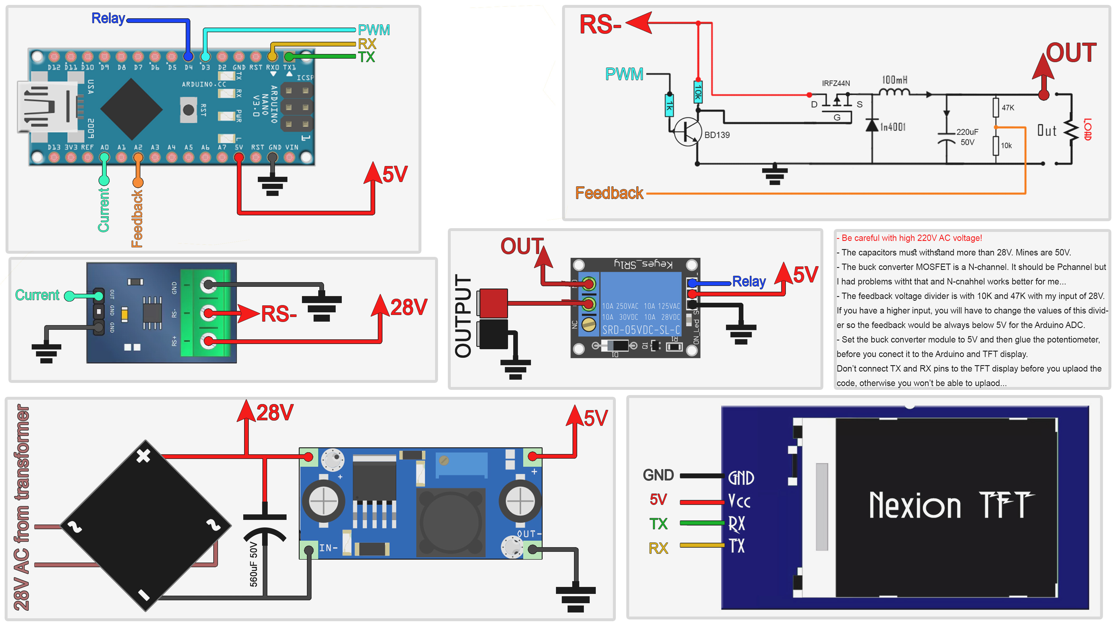
Now we haev the main input of 28V DC and also 5V for the electronics. To control the power supply output, which will be variable, we use the buck converter circuit as in the schematic above. This is controlled by an Arduino NANO with feedback for the output voltage and the current. The current is measured using the max471 module. To enable or disable the output I'm using a relay.
Ok, before we look over the code, remember that the TFT display needs the .tft file to be uplaoded. To see how I've made the .tft file taht goes to the NEXTION display, look over my past tutorial on this link. Once I have the .tft file, put it on a micro SD card and plug that into the display. Make sure the display is not powered on before you add the SD card. Once the card is in the card slot, power up the screen with 5V from the arduino and the new .tft file is uploaded.
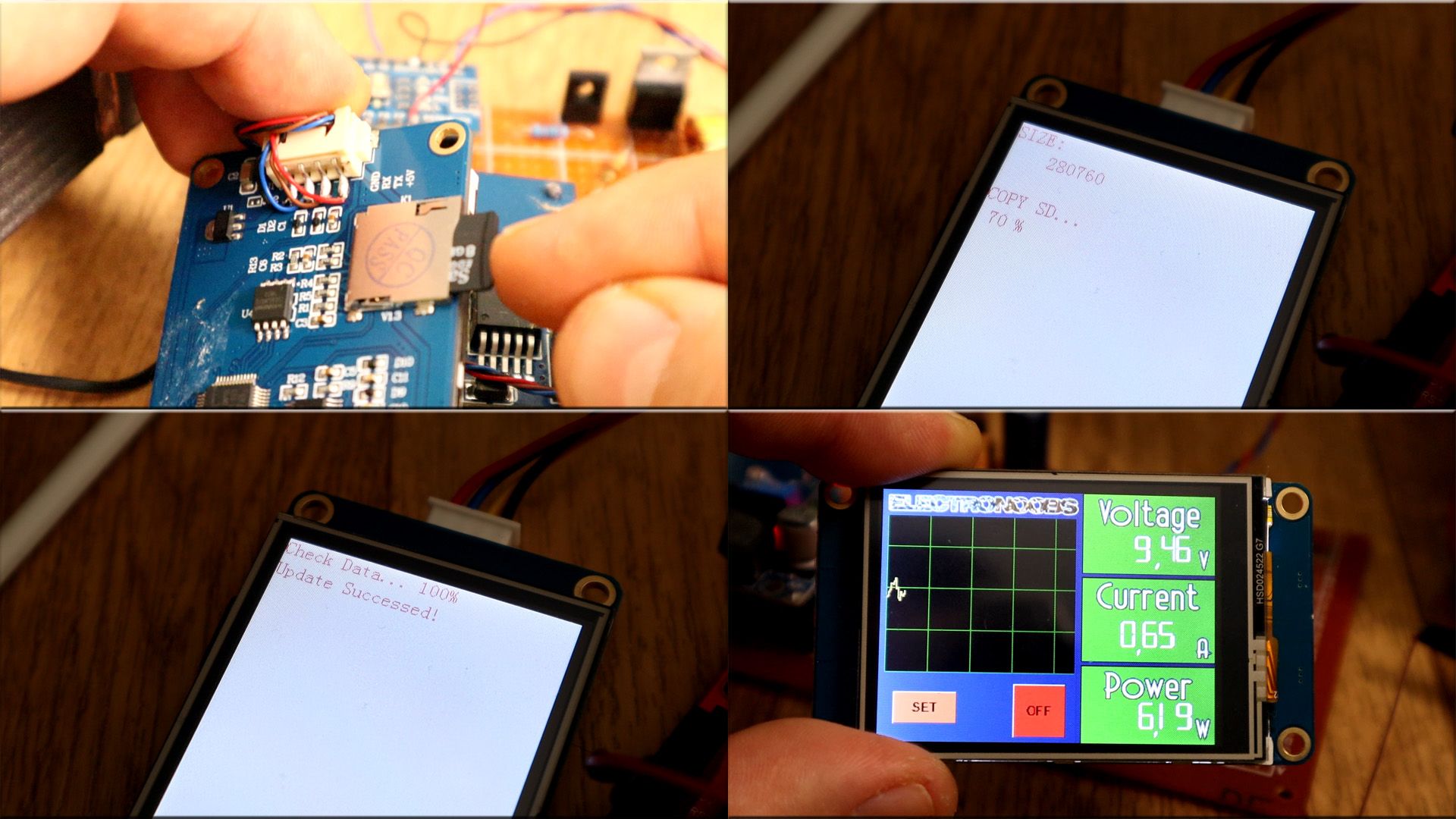
Now power off the display and remove the SD card. Now power it back on and the new graphics are displayed. Is time for the code. Please check last tutorial and see how we communicate with this TFT display. We will use the UART port to receive and send data and by taht change the values on the screen.
Downlaod the code from below. We need no extra libraries. Make sure you disconnect the Rx and Tx pins of the display before you uplaod the code. Otherwise you won't be able to do that. Compile and upload the code. Then connect the display to the Arduino and the rest of the components as in the schematic.
Please read the code line by line and all the comments in the code to understand more. The idea goes like this: We have the real values (current, voltage and power) measured all the time. Then we have the setpoint for each value that is set with the TFT display. Then a crude PID code will control the output according to the setpoints.
In the Setup void we start the serial communication. Usually the default baud rate of the NEXTION display ios 9600 bauds but it could also be 115200. We set the PWM frequency of digital pin 3 to be high using some registers and then we clear the wave on the display.
void setup() {
  Serial.begin(9600);                         //Or change to 115200 if your NEXTION display works at that speed
  pinMode(feedback,INPUT);
  pinMode(current_in,INPUT);
  pinMode(pwm,OUTPUT);
  pinMode(output_enable_pin,OUTPUT);
  digitalWrite(output_enable_pin,LOW);        //output relay turned OFF when we start
  TCCR2B = TCCR2B & B11111000 | B00000001;    // pin 3 and 11 PWM frequency of 31372.55 Hz

  Serial.print("cle 5,255");                  //Send instruction to clear the waveform
  Serial.write(0xff);
  Serial.write(0xff);
  Serial.write(0xff);
}
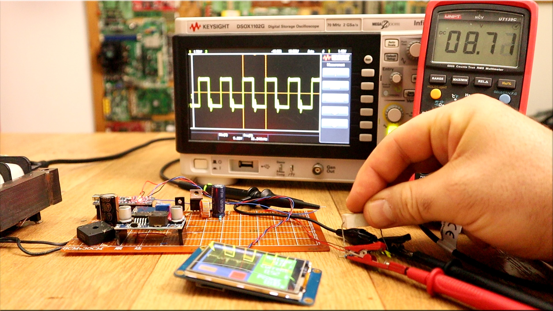
Now with the .tft file uplaoded and the code as well, and the entire schematic mounted I make some tests. I set the output voltage at 10V and a high current limit such as 2A. I now place a load at the output. As you can see in the video below, the output is still 10V but the PWM signal automatically cahnged to a different value in order to keep the same output. So the voltage feedback works.
In the same way, I now set a current limit of 0.5A. I now apply a 15 ohms load. The current at 10V should be higher than 0.5A but since we have a the limit, the voltage will get lower (8,7V) as you can see in the test video below, in order to keep the same current limit. So the current limit works as well
This is not a perfec project but I hope it will teach you how a digital power supply works more or less. If you would like to support me check my PATREON. Thank you.


