
This is a very simple tutorial. Original posts are here on this link. Any way, in this tutorial we will use two pins from the Arduino to create fast PWM signals. With a small filter, we change the amplitude of that signal according to the width of the PWM pulse. By that, we can draw shapes on the oscilloscope when in XY mode.
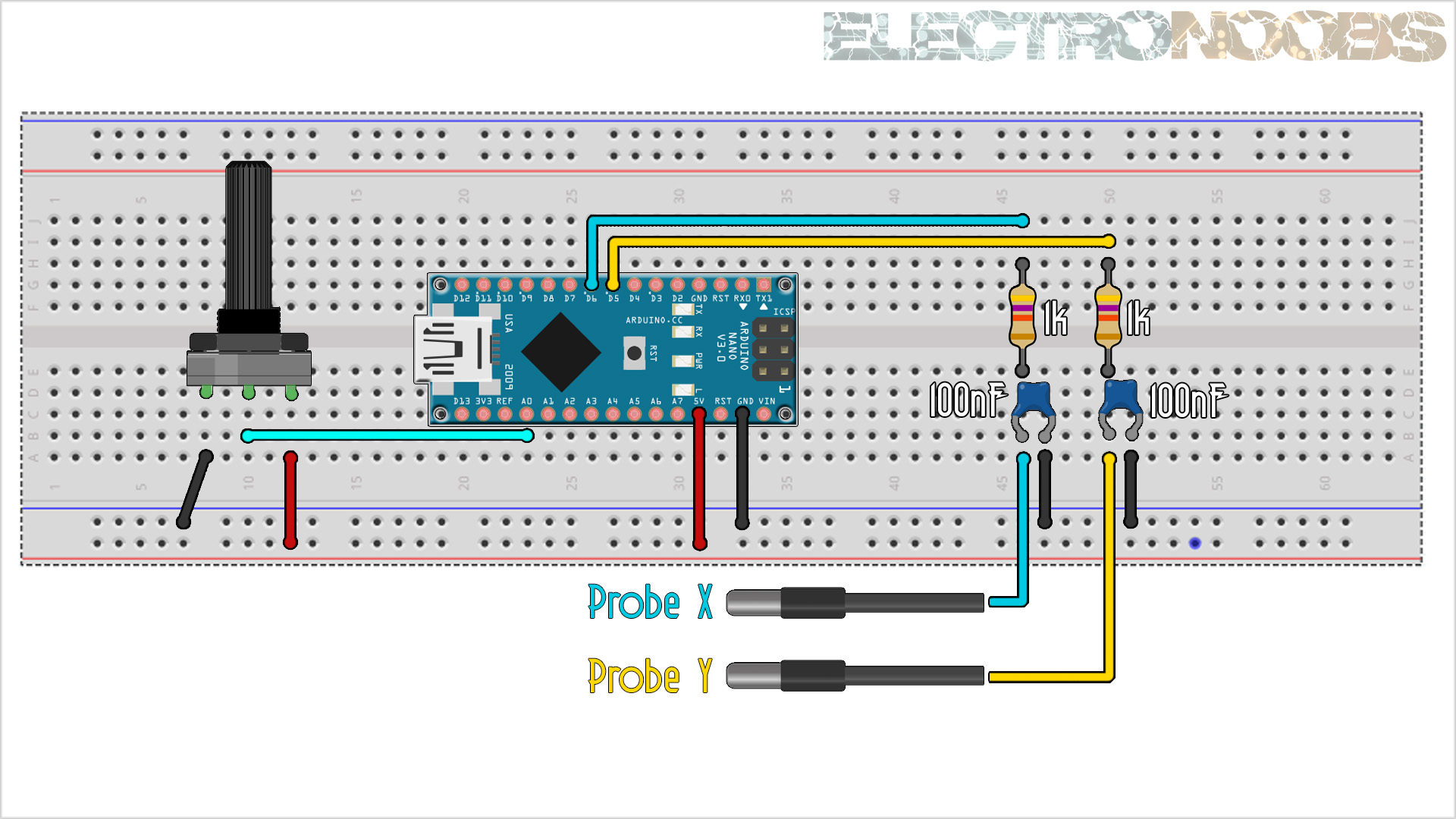
This is the schematic we will use. We need two 1k resistors and two 100nF capacitors to create the filter. We need the Arduino nano to create the signals and a potentiometer to adjust the delay time between each loop. The ouptut of each filter will be connected to the probes of the oscilloscope for X and Y on channels 1 and 2.
First we need the coordinates for our draw. Have in mind it could be up to 254 by 254 units since that is the maximum value of the analogWrite on the Arduino for the PWM signal. So, draw the X and Y axis on a pice of paper. Then add numbers for each square, in my case from 1 to 20 on the X axis and from 1 to 25 on the Y axis. Then, center and create your draw. In my first example I ahve a christmas tree. Next step is to number each vertex. In my case I have from vertex 1 to 19.
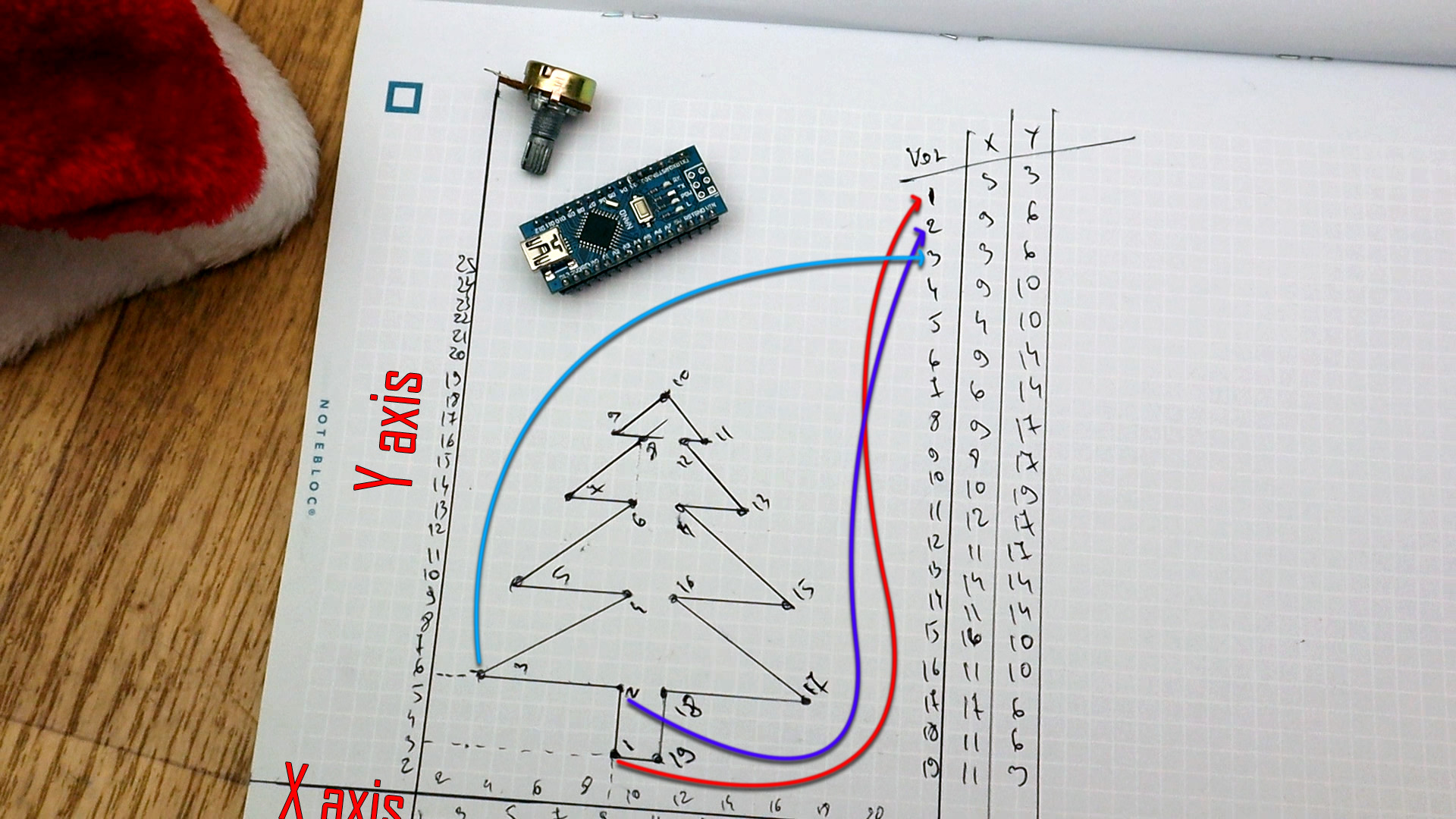
You have to number the vertices in the best way so there are not to much overlaps of the lines. For example if in the picture above instead of going from vertex 1, to 2, 3, 4... I go from 1, 2, 3, 17, 4 etc... it would create a zig-zag image and we don't want that. When you have all the vertices, make a small table and write donw the X and Y coordinates for each point. Now we haev the data.
For the code, I've prepared a few examples. As you can see in the video and picture above, we first need the X and Y coordinates of our draw. Once we have that we need the amount of vertices and put these values in the code.
First, in the code, we define the pins that we will use for the PWM signals. In this case I use pin D6 for the X data and pin D5 for the Y data. It has to be these pins since later in the code we change some registers and change the speed of the PWM signals to a higher value. We also define the pin connected to the potentiometer that will change the delay time for each loop.
//Inputs/Outputs
int X_pin = 6;
int Y_pin = 5;
int Pot = A0;
Then we define the default delay in micro seconds. Then we add how many vertices our draw has, in my case just 19. Then we add the X coordinates in a vector of 19 vertices. We do the same but with the Y vertices and now we have the data prepared.
int point_delay = 1000;         //Delay between loops in us
#define how_many_vertices  19   //Put here the amount of vertices that you ahve
//Coordinates for the X axis (remember, up to 254 coordinates)
byte x_axis[how_many_vertices] = {
  9,9,3,9,4,9,6,9,8,10,12,11,14,11,16,11,17,11,11};
//Coordinates for the Y axis
byte y_axis[how_many_vertices] = {
  3,6,6,10,10,14,14,17,17,19,17,17,14,14,10,10,6,6,3};
In the setup we set the pins as outputs or inputs and then we change some registers. These registers will change the frequency of the PWM signal since the default one is very slow and for our filter we need higher speeds. We can now start the void loop.
void setup() {
  pinMode(X_pin,OUTPUT);      //Define the pin as output
  pinMode(Y_pin,OUTPUT);      //Define the pin as output
  pinMode(Pot,INPUT);         //Define the pin as input for the potentiometer

  //Now we adjust PWM frequency using Prescale_factor
  TCCR0A =  (TCCR0A & B10100011 + TCCR0A | B10100011);  //(1<<COM0A1 | 0<<COM0A0 | 1<<COM0B1 | 0<<COM0B0 | 1<<WGM01 | 1<<WGM00);
  TCCR0B =  (TCCR0B & B00000001 + TCCR0B | B00000001);  //(0<<FOC0A | 0<<FOC0B | 0<<WGM02 | 0<<CS02 | 0<<CS01 | 1<<CS00);
  TIMSK0 =  (TIMSK0 & B11111000);                       //(0<<OCIE0B | 0<<OCIE0A  | 0<<TOIE0);
}
Finally, in the void loop we create a "for" in the range of the amount of vertices. Then we write the analog PWM signal according to the coordinate of the X and Y vector defined above. With that we cand draw shapes. That's it...
void loop() {
  unsigned char loopcount;
  {
    point_delay = map(analogRead(Pot),0,1024,10,2000);                //Read analog value adn map it to a range between 10 and 2000us
    for(loopcount = 0; loopcount < how_many_vertices; loopcount++)
    {
      analogWrite(X_pin,x_axis[loopcount]);                           //In this "for" we change the analog PWM width according to X axis and Y axis
      analogWrite(Y_pin,y_axis[loopcount]);
      delayMicroseconds(point_delay);                                 //Add the delay
    }
  }
}
Upload the code to the Arduino and make the connections as in the schematic. Power the oscilloscope and select XY mode. Then select high resolution so we have better lines. You could also add persistance and get even better lines. Adjust the ch1 and ch2 knobs till you center the draw and that's it.


