


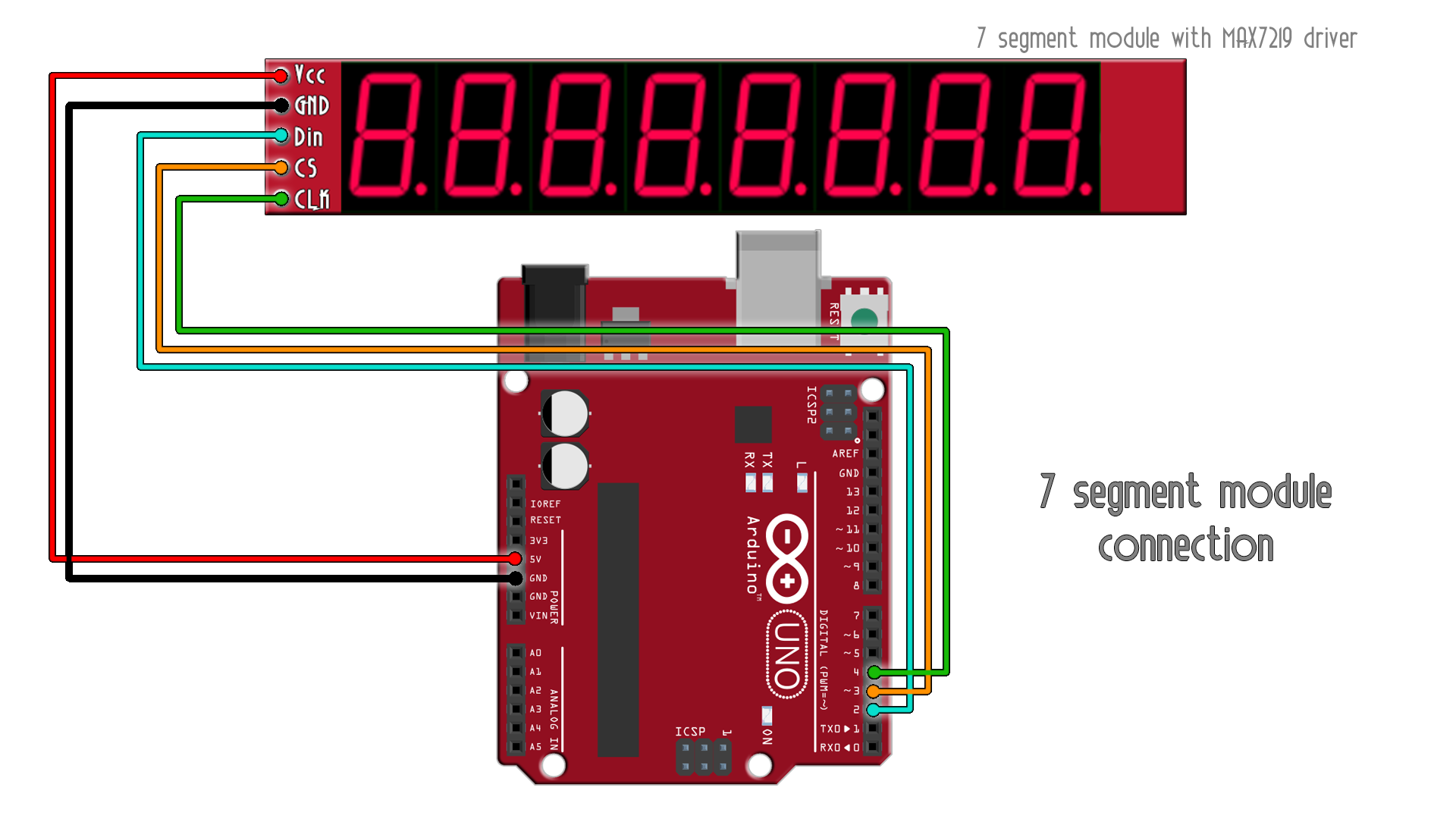
This is a very short example. How to use these kind of mudules with the MAX7219 drivers and control 8 seven segments displays. It uses serial communication so we only need 3 wires for data, clock and CS. We can supply this module at 5V and show numbers, a few letters and 7 decimal points.
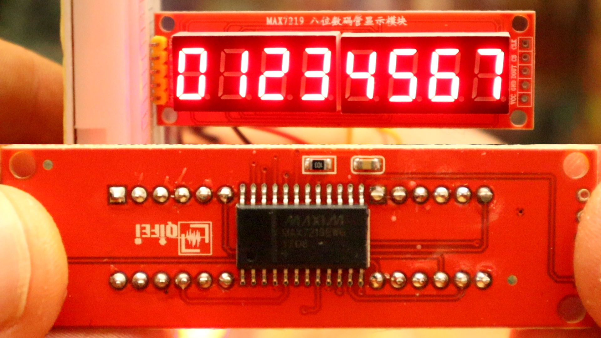
First, you need a 7 segments display like this one on this link. This uses serial data to show up to 8 numbers from 0 to 9 and 7 decimal dots. To send data, all we ahve to do is to shift the bytes on the data pin.
Ok, make the SPI connections as below between the LCD and te Arduino pins. Supply 5V and connect GND as well. To turn ON the backlight you ahve to connect GND to the light pin. Next, go below and downlaod the library and see the example code. Upload the code and test the LCD.
We don't need any library for this example. All we have to do is to send data to the chip by shifting each byte value on the data pin. To know what values we have to send to each register, check this datasheet of this module to know mopre. Then uplaod the test code, make the connections and give it a test.
/*  7 segment display MAX7219 driver serial control
 Schematic: https://www.electronoobs.com/eng_arduino_tut54_sch1.php
 Code: https://www.electronoobs.com/eng_arduino_tut54_code1.php
*/

#define MAX7219_Data_IN 2
#define MAX7219_Chip_Select  3
#define MAX7219_Clock 4

byte adr = 0x08;
byte num = 0x00;
int i = 0;

void shift(byte send_to_address, byte send_this_data)
{
  digitalWrite(MAX7219_Chip_Select, LOW);
  shiftOut(MAX7219_Data_IN, MAX7219_Clock, MSBFIRST, send_to_address);
  shiftOut(MAX7219_Data_IN, MAX7219_Clock, MSBFIRST, send_this_data);
  digitalWrite(MAX7219_Chip_Select, HIGH);
}


void setup() {
  pinMode(MAX7219_Data_IN, OUTPUT);
  pinMode(MAX7219_Chip_Select, OUTPUT);
  pinMode(MAX7219_Clock, OUTPUT);
  digitalWrite(MAX7219_Clock, HIGH);
  delay(200);

  //Setup of MAX7219 chip
  shift(0x0f, 0x00); //display test register - test mode off
  shift(0x0c, 0x01); //shutdown register - normal operation
  shift(0x0b, 0x07); //scan limit register - display digits 0 thru 7
  shift(0x0a, 0x0f); //intensity register - max brightness
  shift(0x09, 0xff); //decode mode register - CodeB decode all digits

}

void loop() {

  //Data transfer
  shift(0x08, 0x00); //digit 7 (leftmost digit) data
  shift(0x07, 0x01);
  shift(0x06, 0x02);
  shift(0x05, 0x03);
  shift(0x04, 0x04);
  shift(0x03, 0x05);
  shift(0x02, 0x06);
  shift(0x01, 0x07); //digit 0 (rightmost digit) data
  delay(1000);
  shift(0x08, 0x07); //digit 7 (leftmost digit) data
  shift(0x07, 0x06);
  shift(0x06, 0x05);
  shift(0x05, 0x04);
  shift(0x04, 0x03);
  shift(0x03, 0x02);
  shift(0x02, 0x01);
  shift(0x01, 0x00); //digit 0 (rightmost digit) data
  delay(1000);
}


