


Download the .zip file below. Open the Arduino (.ino) code on your Arduino IDE and upload it to the Arduino NANO. Make sure you have connections in the schematic below. You could downlaod the code from the link below or also copy and paste the code from below.
/* http://www.youtube.com/c/electronoobs
*
* This is an example for the 3D printed gimbal project. It uses
* the MPU6050 and two S3003 servo motors. This is the PID code for the gimbal. *
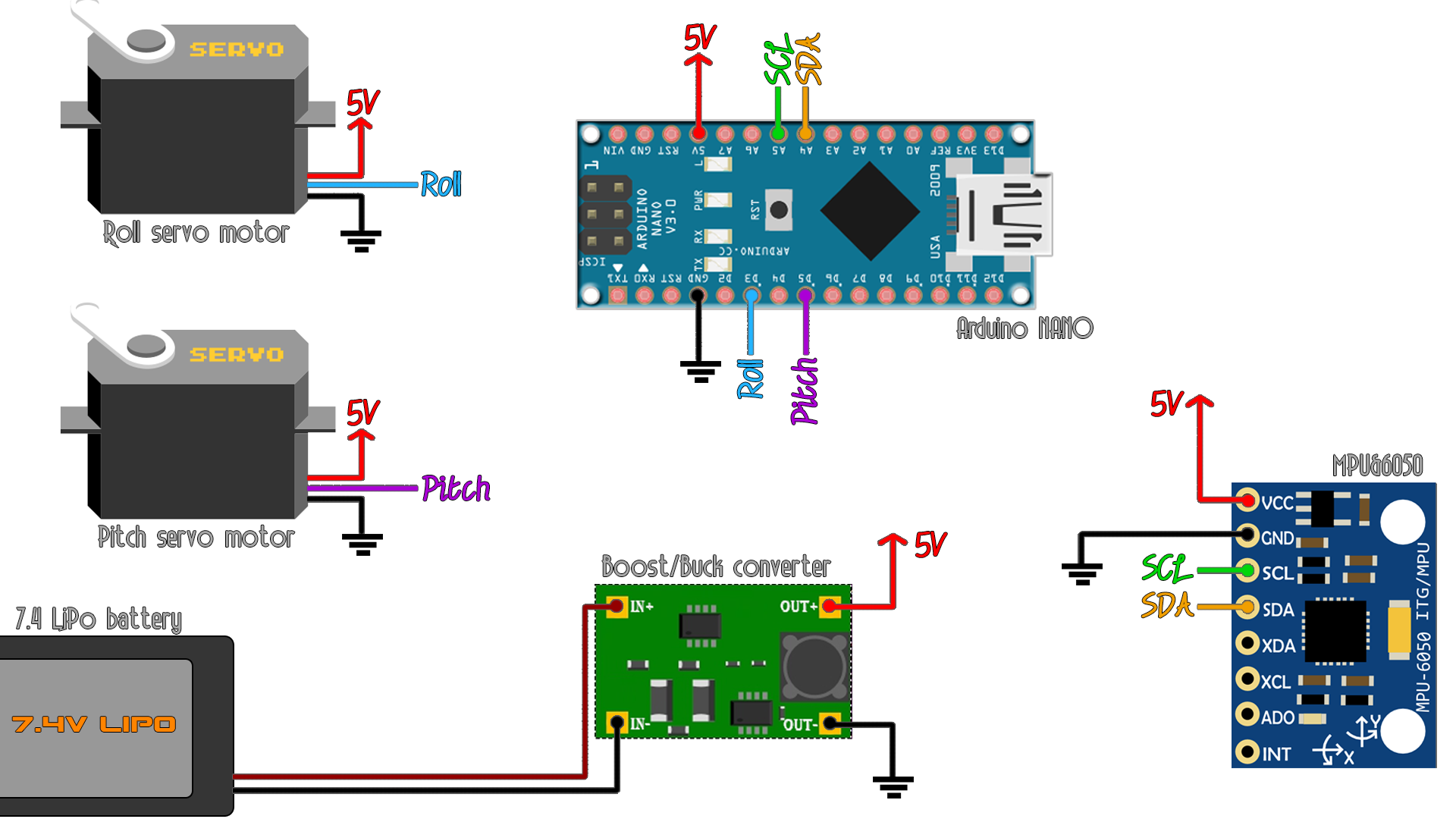
* Arduino pin | MPU6050
* 5V | Vcc
* GND | GND
* A4 | SDA
* A5 | SCL
* Scheematic: https://www.electronoobs.com/eng_arduino_tut46_sch1.php
*/
//Includes
#include <Wire.h>
#include <Servo.h>
Servo pitch;
Servo roll;
/*MPU-6050 gives you 16 bits data so you have to create some float constants
*to store the data for accelerations and gyro*/
//Gyro Variables
float elapsedTime, time, timePrev; //Variables for time control
int gyro_error=0; //We use this variable to only calculate once the gyro data error
float Gyr_rawX, Gyr_rawY, Gyr_rawZ; //Here we store the raw data read
float Gyro_angle_x, Gyro_angle_y; //Here we store the angle value obtained with Gyro data
float Gyro_raw_error_x, Gyro_raw_error_y; //Here we store the initial gyro data error
//Acc Variables
int acc_error=0; //We use this variable to only calculate once the Acc data error
float rad_to_deg = 180/3.141592654; //This value is for pasing from radians to degrees values
float Acc_rawX, Acc_rawY, Acc_rawZ; //Here we store the raw data read
float Acc_angle_x, Acc_angle_y; //Here we store the angle value obtained with Acc data
float Acc_angle_error_x, Acc_angle_error_y; //Here we store the initial Acc data error
float Total_angle_x, Total_angle_y; //Here we store the final total angle
//More variables for the code...
int i;
int mot_activated=0;
long activate_count=0;
long des_activate_count=0;
//////////////////////////////PID FOR ROLL///////////////////////////
float roll_PID, pwm_L_F, pwm_L_B, pwm_R_F, pwm_R_B, roll_error, roll_previous_error;
float roll_pid_p=0;
float roll_pid_i=0;
float roll_pid_d=0;
///////////////////////////////ROLL PID CONSTANTS////////////////////
double roll_kp=4;//3.55
double roll_ki=0.1;//0.003
double roll_kd=0.1;//2.05
float roll_desired_angle = 0; //This is the angle in which we whant the
//////////////////////////////PID FOR PITCH//////////////////////////
float pitch_PID, pitch_error, pitch_previous_error;
float pitch_pid_p=0;
float pitch_pid_i=0;
float pitch_pid_d=0;
///////////////////////////////PITCH PID CONSTANTS///////////////////
double pitch_kp=4;//3.55
double pitch_ki=0.1;//0.003
double pitch_kd=0.1;//2.05
float pitch_desired_angle = 0; //This is the angle in which we want the gimbal to stay (for now it will be 0) Joystick for future versions
float PWM_pitch, PWM_roll;
void setup() {
pitch.attach(5); //servo motor for pitch
roll.attach(3); //servo motor for roll
Wire.begin();
//begin the wire comunication
Wire.beginTransmission(0x68); //begin, Send the slave adress (in this case 68)
Wire.write(0x6B); //make the reset (place a 0 into the 6B register)
Wire.write(0x00);
Wire.endTransmission(true); //end the transmission
//Gyro config
Wire.beginTransmission(0x68); //begin, Send the slave adress (in this case 68)
Wire.write(0x1B); //We want to write to the GYRO_CONFIG register (1B hex)
Wire.write(0x10); //Set the register bits as 00010000 (1000dps full scale)
Wire.endTransmission(true); //End the transmission with the gyro
//Acc config
Wire.beginTransmission(0x68); //Start communication with the address found during search.
Wire.write(0x1C); //We want to write to the ACCEL_CONFIG register
Wire.write(0x10); //Set the register bits as 00010000 (+/- 8g full scale range)
Wire.endTransmission(true);
//Serial.begin(9600); //Remember to set this same baud rate to the serial monitor
time = millis(); //Start counting time in milliseconds
}//end of setup void
void loop() {
/////////////////////////////I M U/////////////////////////////////////
timePrev = time; // the previous time is stored before the actual time read
time = millis(); // actual time read
elapsedTime = (time - timePrev) / 1000;
/*The tiemeStep is the time that elapsed since the previous loop.
*This is the value that we will use in the formulas as "elapsedTime"
*in seconds. We work in ms so we have to divide the value by 1000
to obtain seconds*/
/*Reed the values that the accelerometre gives.
* We know that the slave adress for this IMU is 0x68 in
* hexadecimal. For that in the RequestFrom and the
* begin functions we have to put this value.*/
//////////////////////////////////////Gyro read/////////////////////////////////////
Wire.beginTransmission(0x68); //begin, Send the slave adress (in this case 68)
Wire.write(0x43); //First adress of the Gyro data
Wire.endTransmission(false);
Wire.requestFrom(0x68,4,true); //We ask for just 4 registers
Gyr_rawX=Wire.read()<<8|Wire.read(); //Once again we shif and sum
Gyr_rawY=Wire.read()<<8|Wire.read();
/*Now in order to obtain the gyro data in degrees/seconds we have to divide first
the raw value by 32.8 because that's the value that the datasheet gives us for a 1000dps range*/
/*---X---*/
Gyr_rawX = (Gyr_rawX/32.8);
/*---Y---*/
Gyr_rawY = (Gyr_rawY/32.8);
/*Now we integrate the raw value in degrees per seconds in order to obtain the angle
* If you multiply degrees/seconds by seconds you obtain degrees */
/*---X---*/
Gyro_angle_x = Gyr_rawX*elapsedTime;
/*---X---*/
Gyro_angle_y = Gyr_rawY*elapsedTime;
//////////////////////////////////////Acc read/////////////////////////////////////
Wire.beginTransmission(0x68); //begin, Send the slave adress (in this case 68)
Wire.write(0x3B); //Ask for the 0x3B register- correspond to AcX
Wire.endTransmission(false); //keep the transmission and next
Wire.requestFrom(0x68,6,true); //We ask for next 6 registers starting withj the 3B
/*We have asked for the 0x3B register. The IMU will send a brust of register.
* The amount of register to read is specify in the requestFrom function.
* In this case we request 6 registers. Each value of acceleration is made out of
* two 8bits registers, low values and high values. For that we request the 6 of them
* and just make then sum of each pair. For that we shift to the left the high values
* register (<<) and make an or (|) operation to add the low values.
If we read the datasheet, for a range of+-8g, we have to divide the raw values by 4096*/
Acc_rawX=(Wire.read()<<8|Wire.read())/4096.0 ; //each value needs two registres
Acc_rawY=(Wire.read()<<8|Wire.read())/4096.0 ;
Acc_rawZ=(Wire.read()<<8|Wire.read())/4096.0 ;
/*Now in order to obtain the Acc angles we use euler formula with acceleration values
after that we substract the error value found before*/
/*---X---*/
Acc_angle_x = (atan((Acc_rawY)/sqrt(pow((Acc_rawX),2) + pow((Acc_rawZ),2)))*rad_to_deg) ;
/*---Y---*/
Acc_angle_y = (atan(-1*(Acc_rawX)/sqrt(pow((Acc_rawY),2) + pow((Acc_rawZ),2)))*rad_to_deg) ;
//////////////////////////////////////Total angle and filter/////////////////////////////////////
/*---X axis angle---*/
Total_angle_x = 0.98 *(Total_angle_x + Gyro_angle_x) + 0.02*Acc_angle_x;
/*---Y axis angle---*/
Total_angle_y = 0.98 *(Total_angle_y + Gyro_angle_y) + 0.02*Acc_angle_y;
//Uncomment this below for debug
/*
Serial.print("GyroX angle: ");
Serial.print(Total_angle_x);
Serial.print(" | ");
Serial.print("GyroY angle: ");
Serial.println(Total_angle_y);*/
/*///////////////////////////P I D///////////////////////////////////*/
roll_desired_angle = 0; //The angle we want the gimbal to stay is 0 and 0 for both axis for now...
pitch_desired_angle = 0;
/*First calculate the error between the desired angle and
*the real measured angle*/
roll_error = Total_angle_y - roll_desired_angle;
pitch_error = Total_angle_x - pitch_desired_angle;
/*Next the proportional value of the PID is just a proportional constant
*multiplied by the error*/
roll_pid_p = roll_kp*roll_error;
pitch_pid_p = pitch_kp*pitch_error;
/*The integral part should only act if we are close to the
desired position but we want to fine tune the error. That's
why I've made a if operation for an error between -2 and 2 degree.
To integrate we just sum the previous integral value with the
error multiplied by the integral constant. This will integrate (increase)
the value each loop till we reach the 0 point*/
if(-3 < roll_error <3)
{
roll_pid_i = roll_pid_i+(roll_ki*roll_error);
}
if(-3 < pitch_error < 3)
{
pitch_pid_i = pitch_pid_i+(pitch_ki*pitch_error);
}
/*The last part is the derivate. The derivate acts upon the speed of the error.
As we know the speed is the amount of error that produced in a certain amount of
time divided by that time. For taht we will use a variable called previous_error.
We substract that value from the actual error and divide all by the elapsed time.
Finnaly we multiply the result by the derivate constant*/
roll_pid_d = roll_kd*((roll_error - roll_previous_error)/elapsedTime);
pitch_pid_d = pitch_kd*((pitch_error - pitch_previous_error)/elapsedTime);
/*The final PID values is the sum of each of this 3 parts*/
roll_PID = roll_pid_p + roll_pid_i + roll_pid_d ;
pitch_PID = pitch_pid_p + pitch_pid_i + pitch_pid_d ;
/*We know taht the min value of PWM signal is -90 (usingservo.write) and the max is 90. So that
tells us that the PID value can/s oscilate more than -90 and 90 so we constrain those values below*/
if(roll_PID < -90){roll_PID = -90;}
if(roll_PID > 90) {roll_PID = 90; }
if(pitch_PID < -90){pitch_PID = -90;}
if(pitch_PID > 90) {pitch_PID = 90;}
roll_previous_error = roll_error; //Remember to store the previous error.
pitch_previous_error = pitch_error; //Remember to store the previous error.
PWM_pitch = 90 + pitch_PID; //Angle for each motor is 90 plus/minus the PID value
PWM_roll = 90 - roll_PID;
pitch.write(PWM_pitch); //Finally we write the angle to the servos
roll.write(PWM_roll);
}//end of void loop


