


This is another very simple project and kind of geeky. I’ve made my own digital watch. If you think there is nothing to learn with this simple project, well, you’re wrong. We will learn how to use the ATmega328p - AU chip without an external clock by burning an 8MHz internal clock bootloader. The chip will work at low voltage, 3.2 volts from a button cell battery. The battery has low capacity, so, we need a low consumption.
I’ve used easy EDA and create my schematic. You have both the schematic and GERBERS together with the part list for this PCB, below, if you want to make this same project. I place the ATmega328p- AU version of the chip, the LEDs and resistors, few capacitors and the button and that’s it. The schematic is so simple. I create a new LAYOUT and give the shape of a watch. After I place the components and route all the tracks, I fill the board with copper and add all the extra texts on the silk layer. Check for errors, save, and generate GERBERS. I select order from JLCPCB and that will open a new window and there you can order PCBs.
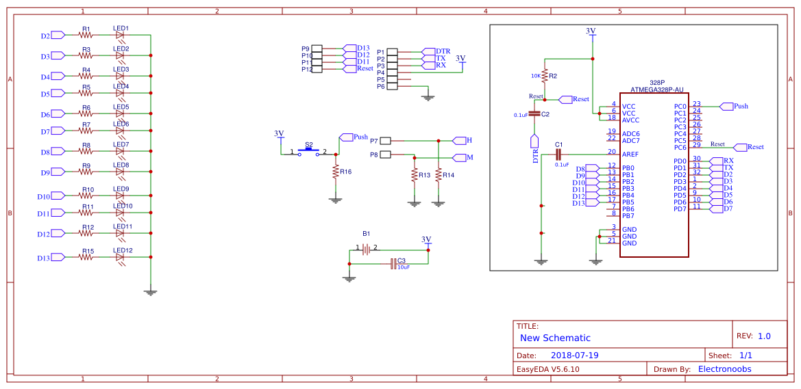
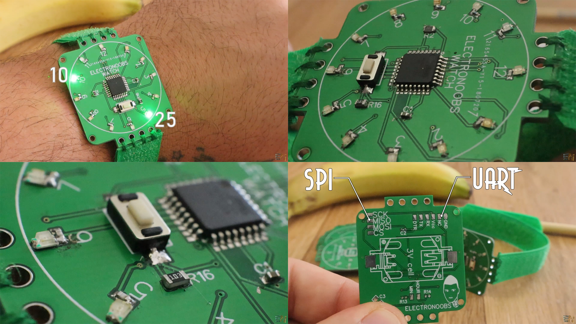
As you can see, the design is simple. We have the ATmega chip in the middle and 12 LEDs all around, each with a 200 ohms resistor to limit the current. We also have a push button with a pulldown that will control everything. On the back, we have space for a 3V button cell socket and some pads for the SPI and UART communication ports. Why? Well, we need the SPI pins to burn the bootloader and the UART port to upload a code and we will see that in a moment.
7 days later I receive 10 boards in a cardboard box and also a small gift. After a quick inspection of the trackas and all the pads and sizes, I gather the components and start soldering.
I first solder a virgin ATmega328 chip. I put some solder paste, place the chip and reflow it with the hot air gun. It has to be bran-new chip in order to burn the 8Mhz internal clock bootloader. I’ve tried with other chips that had the 16Mhz external bootloader and it didn’t work so I recommend you to order some bran-new chips.
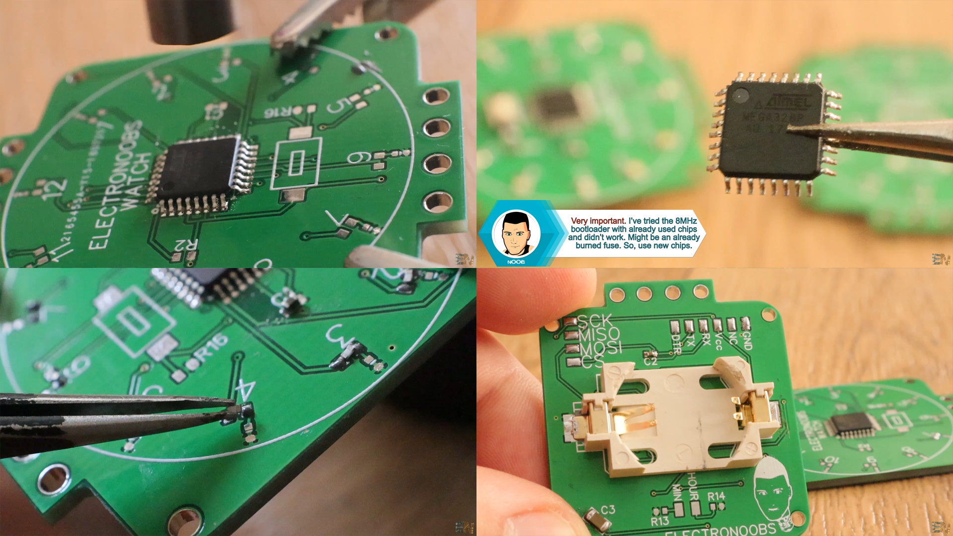
Then I solder 12 x 200 ohms resistors for each LED. I’ve used 0402 size which is very, very, small so I had to use solder paste and a hot air gun to solder all the components for this project. Now for the LED’s, I’ve ordered 20 red 0402 LEDs, but the seller from eBay only sent me 10. Sometimes that happens. So, I had to use 0805 size which are bigger, but with some solder paste and carefully heating each LED, the components got soldered from below so that’s great. I solder the button and its pulldown resistor, and on the back, I solder the battery socket and we are ready to burn the bootloader.
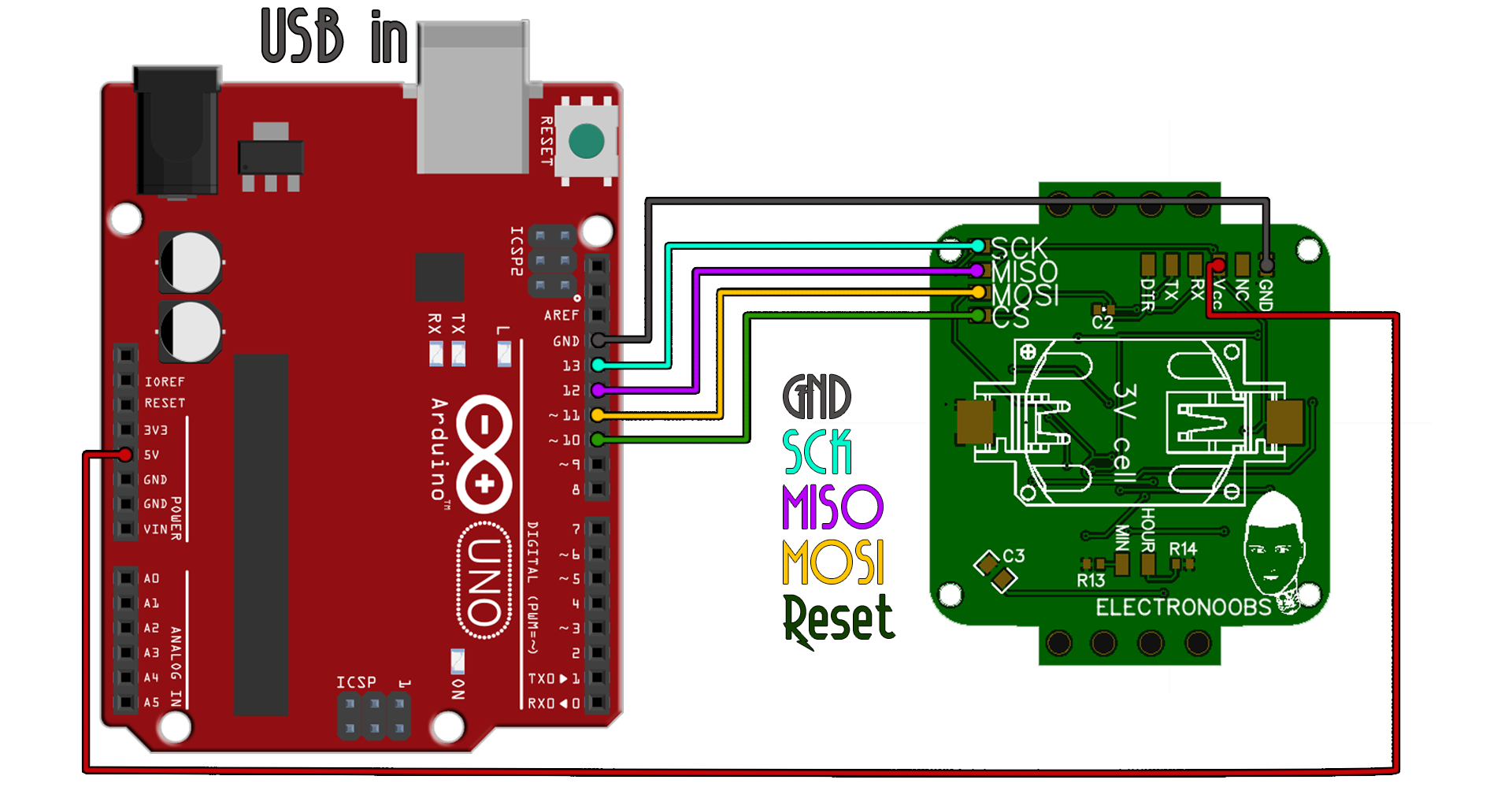
For that I’ve used an Arduino UNO. Make these connections below from the Arduino UNO and the SPI pads on the back of the watch. Make sure to solder GND and Vcc pins as well as in the schematic.
Now, go below and download the breadboard.zip file. This file will give us the 8MHZ on breadboard type of board. Copy the breadboard folder from inside the ZIP file and go to your Arduino directory, to hardware and paste that folder there. If there is no hardware folder, create a new one and name it like that and after paste the breadboard folder inside.
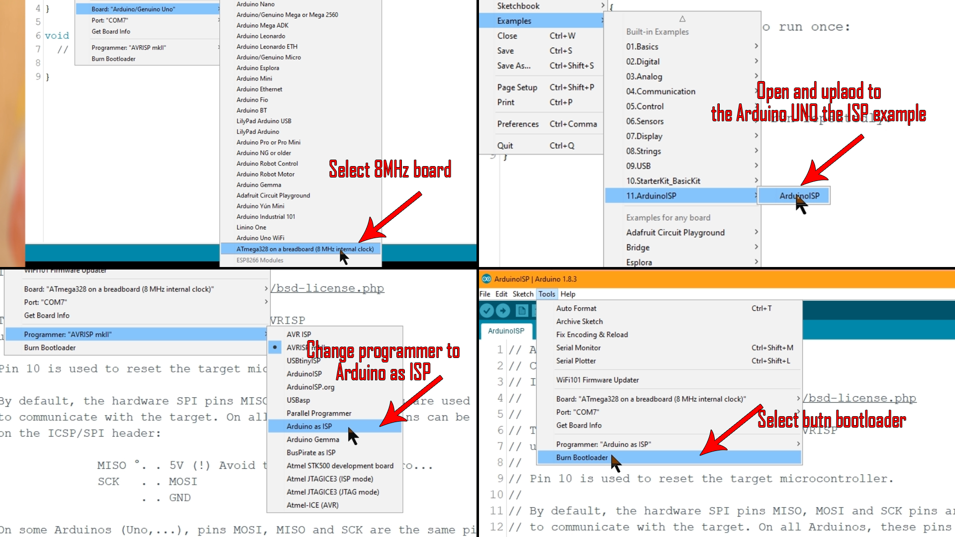
Now run Arduino IDE. If I go now to Tools → boards, I have the ATmega328 on a breadboard with 8MHz internal clock board. Select that. Now go to examples → Arduino ISP and open that example. Connect the Arduino UNO to the PC, select the com and upload the code to the Arduino UNO.
Now, go to tools, make sure once again that the 8Mhz board is selected, and change the programmer from Arduino AVR ISP to Arduino as ISP.
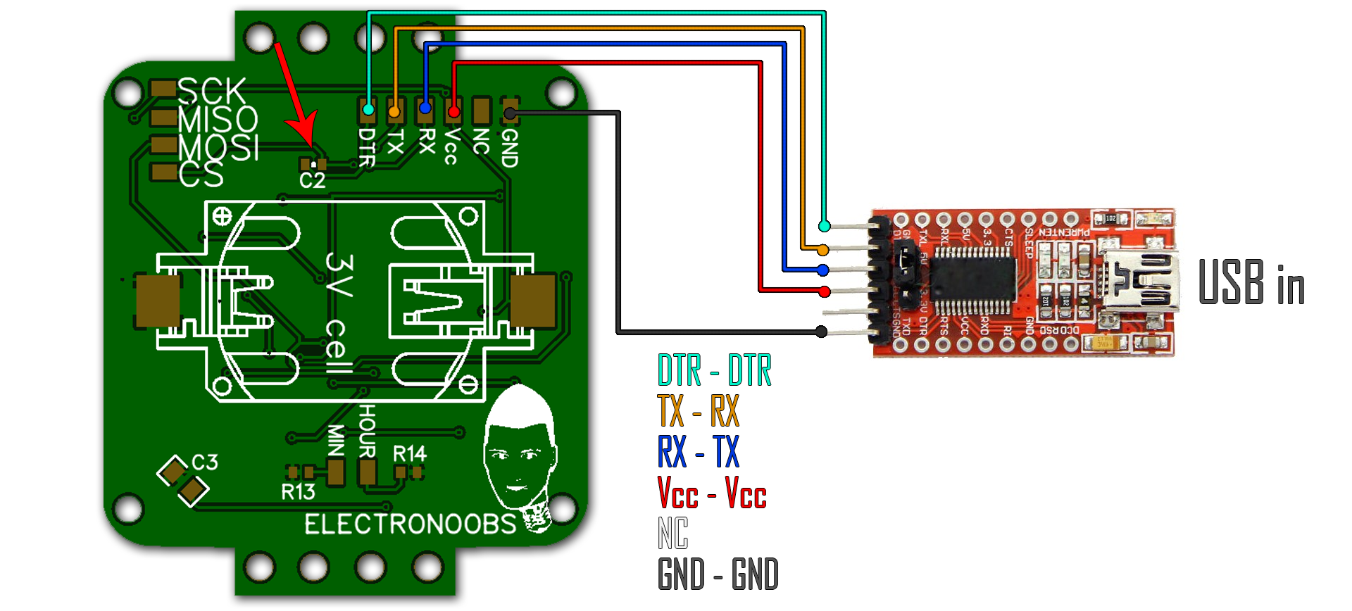
No go to tools once again and select, burn bootloader, and the LEDs of the Arduino will blink fast and now the bootloader is burned to the new ATMEGA chip. So, remove the wires and let’s upload the code. For that you will need an FTDI programmer or maybe use the Arduino UNO UART pins. You have both schematics for that below.
I connect my FTDI programmer to the UART pins. In the Arduino IDE change the programmer back to AVR ISP and upload the new code for 8MHz internal clock board, and that’s it. I’ve made my own watch. Be careful, you will definitely need the 100nF (C2 on layout) capacitor between the DTR pin and reset pin in order to upload codes, so make sure you solder that before uploading.
void setup() {
  //Serial.begin(9600);
  PCICR |= B00000111;    //enable port C o have interrupts
  PCMSK1 |= B00000001;  //Set pin D11 (increase button) trigger an interrupt on state change.

  power_adc_disable(); // ADC converter
  power_spi_disable(); // SPI
  power_usart0_disable();// Serial (USART)
  //power_timer0_disable();// Timer 0
  power_timer1_disable();// Timer 1
  power_timer2_disable();// Timer 2
  power_twi_disable(); // TWI (I2C)


  DDRD = B11111100;   //Set pins D2-D7 as outputs
  DDRB = B00111111;   //Set pins D8-D13 as outputs
  pinMode(A0,INPUT);
}
Now, the code is very long but don’t worry. A lot of the liens are repeating since I make the same instruction for each LED and for each hour or minute. Download it and read all the comments line by line in order to understand more. To reduce power consumption, I disable the ADC, the SPI and UART communications and timer 1 and 2. I live timer 0 active since that will control the millis function. And I use that function to count the elapsed seconds, minutes and hours. Since the ADC is disabled, and the button is connected to analog input A0, I’ve activated interruptions for that pin using these registers.
In the interruption vector I enable the ADC and after I finish the hour display, I disable it back.
Each 1000 miliseconds, I increase the seconds value by one. And each 60 seconds the minutes value and each 60 minutes the hours value. Read the code for more details.
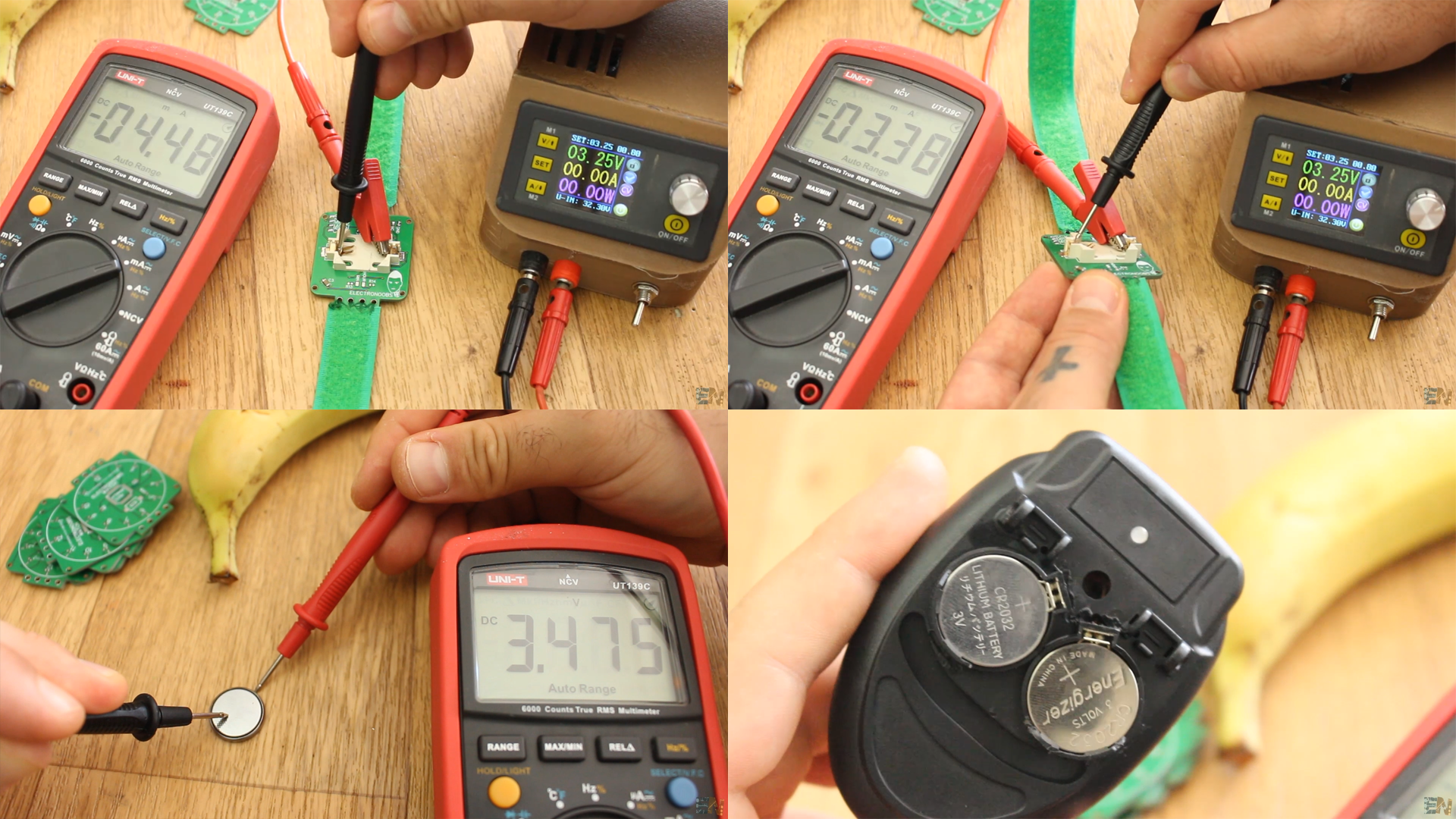
Now I measure the battery voltage and it is 3.47 volts. Using the low consumption mode of the chip, at that voltage the board draws around 3.5mA of current and around 6 or 7mA when the button is pressed. The battery has a capacity of 320mAh, so, it should last around 90 hours or almost 4 days. But, since the voltage will drop, and the chip won’t work with voltages below 2.7V, I can say that it could last around 2 days.
For that I’ve bought this cell battery charger for 2 dollars and use rechargeable batteries. It is not the most efficient project but it looks good and makes you look like a geek. At the end, I’ve used Velcro strip and make a belt for the watch so I could war it on my arm and also screwed a back plate so the battery socket won’t hurt my skin. Not I think it looks pretty decent, right?
So, guys this was how I’ve made this simple and small project. Now you know hot to use the chip without the external crystal and how to add a few lines of code for low power mode. I have to say that I’ve also tried the ultra-low consumption mode and the current was only 0.8uA, which is extremely low. But, unfortunately, with that mode the counters and all the extra parts of the code can’t work, so the time value won’t increase.


