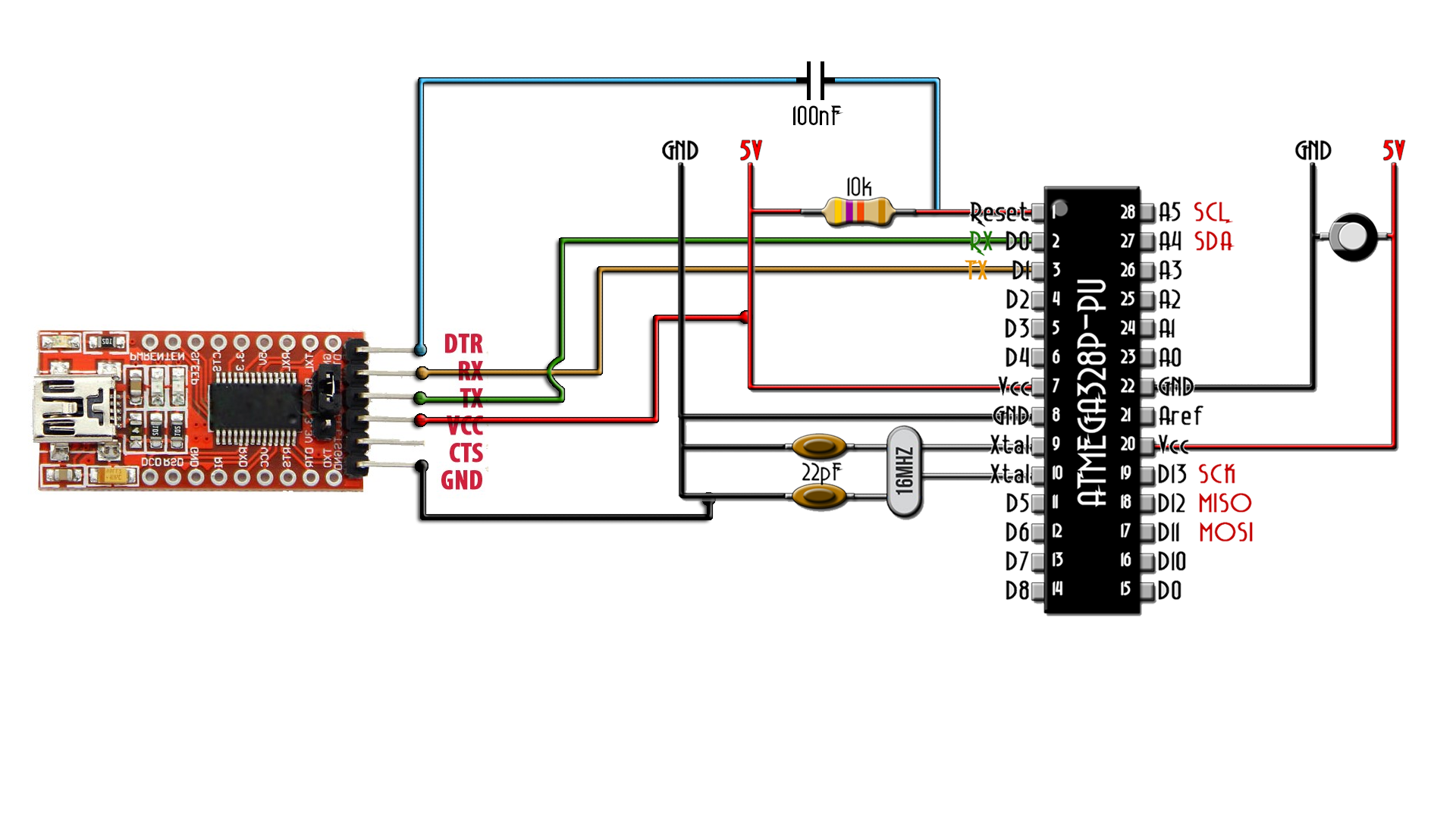
The Arduino uses the ATMega328p chip. We can get that in a SMD format (ATMega328p-AU) or the DIP format for trough hole soldering (ATMega328p-PU). But, the chip by itself can't work. It needs a few more components and all together is called the bare minimum configuration of this chip.
Below we have the schematic for this configuration. As you can see we need a supply of 5 volts. This supply has to be very well regulated with no voltage spikes. For taht and extra 10uF capacitor between 5V and GND. Alos, the reset pin is engative enabeled. So, in order to have it deisabeled, we need to apply 5V to it. For that, a 10k ohms resistor is placed between RESET and Vcc.
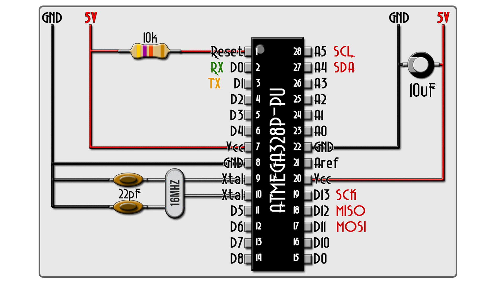
Also, the ATMega328, usually works at 16MHz. For that, between pins 9 and 10 we palce a 16MHz crystal. But this crystal, in order to oscillate needs two capacitors of exactly 22pF connected to GND. In the figure abve, you have all the pins of the chip. Right now, if the microcontroller has a bootlaoder, we could upload a code. But let's imagine it doesn't have a bootloader.
Now, let's imagine the chip doesn't have the bootloder (virgin chip). For that you have to make next connections from an Arduino UNO. These are the SPI pins, CLOCK, MISO and MOSI.
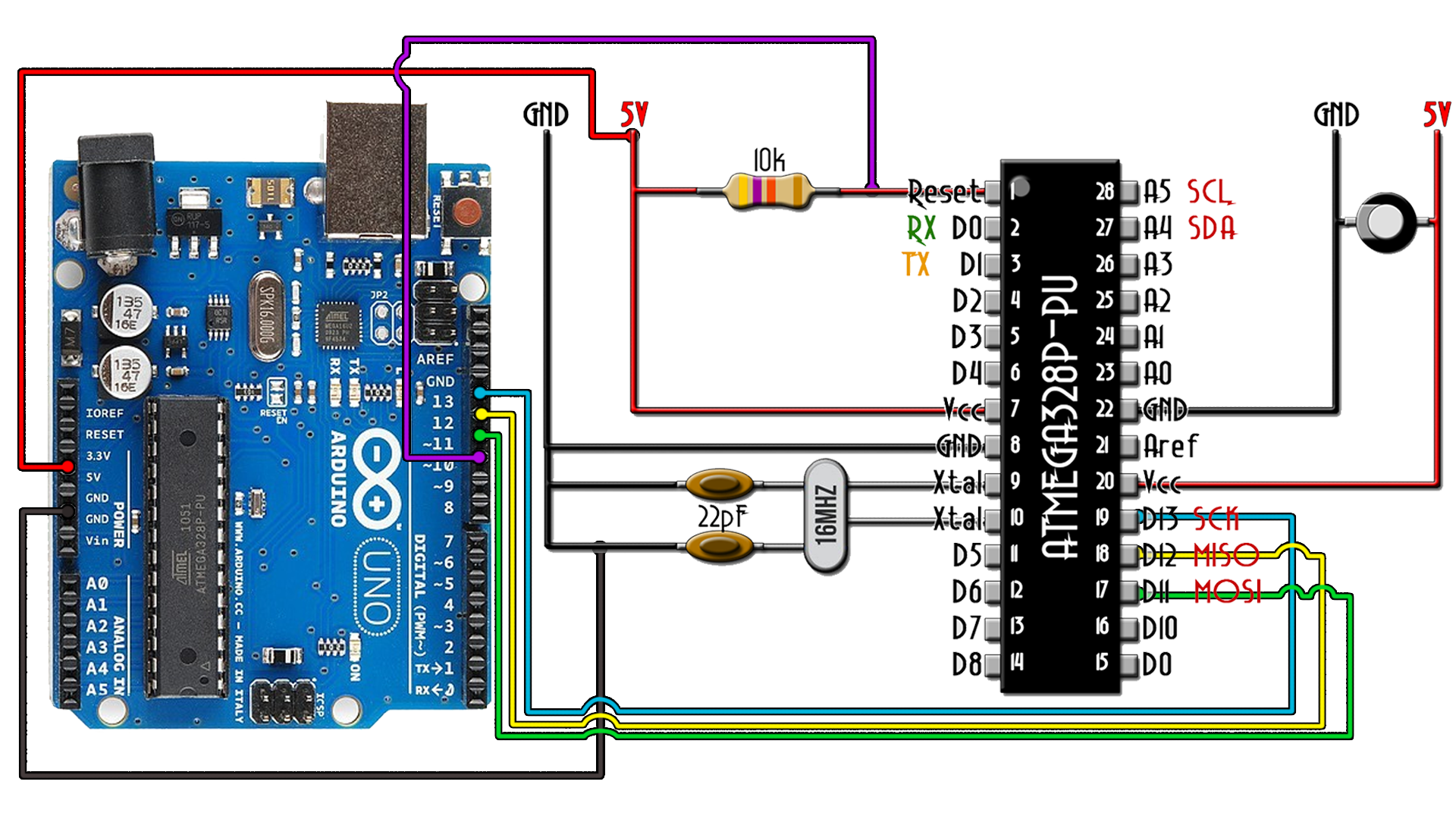
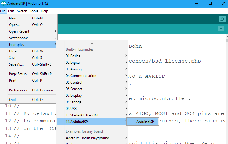
Now connect the Arduino to your PC. Open Arduino IDE and go to File → Examples → Arduino ISP and open that example. Select the com of the Arduino UNO board, select the boar as Arduino UNO and uplaod this code.
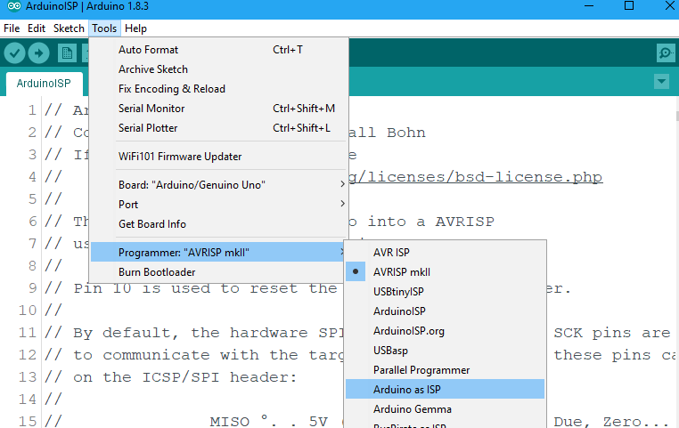
Now make the connections in the past schematicand is time to burn the bootloader. Go to Tools → programmer → Arduino as ISP. By that we change the programmer to ISP.
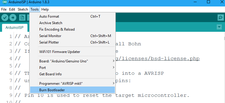
Finally, go to Tools → Burn bootloader. Now the LEDs of the Arduino will blink a lot. Once you get the message of bootlaoder burned we are good to go.
Now, we have the bootloader so we can communicate with the RX and TX pins and upload a code. For that we need and FTDI module. Make the enxt connections and uploade your code.