What’s up my friends, welcome back. Today we will build a homemade slider, I’ll show you how I’ve build it starting with the 3D printed parts, all the mechanical parts, the step motor and finally the electronics. It has a control case with a rotary encoder menu and LCD screen for speed and direction control. The slide uses metal bearings and metal tubes and the rest of the parts are designed and 3D printed. It has a length of 1 meter and can slide to the left or right at adjustable speed and also quite precise because it is using a step motor. So, let’s gather all the parts and see how to build and program our own slider for cameras. So, let’s get started.
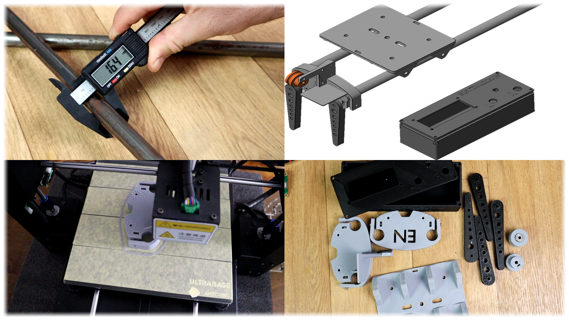
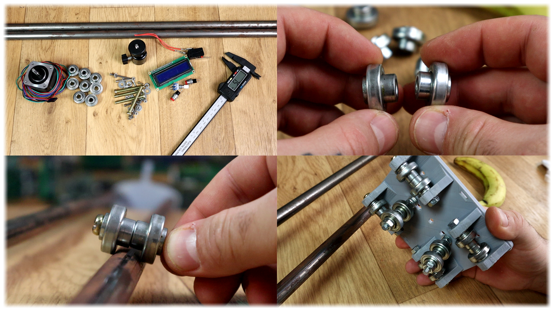
What’s up my friends, welcome back. The first thing to do was to measure the diameter of two metal tubes. Also, of a NEMA 17 step motor, some bearings, the size of a bunch of screws, the camera support, an LCD and all the extra parts. Once I had all the parts dimensions I’ve started editing the plastic parts for this slider. I’ve made the left and right side of the slider and the main plate. Also 4 legs so you could adjust the height and angle of the slider.
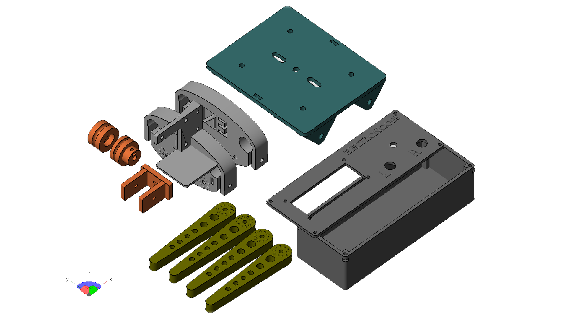
I’ve also designed a case where I’ll place the LCD and all the controls but also the Arduino NANO, and a driver IC for the step motor. All the designs have holes for screws so you could tight all the parts in place. Screws for the left and right sides of the slider to fit those in place on the metal tubes, also screws for the step motor and for closing the main control case.
By the way, in the link below you will find the 3D files of this project and also the dimensions.
I’ve used my 3D printers and printed the 3D files using gray and black PLA material with 20% infill and a 0.4 mm nozzle and a layer height of 0.3mm. These are all the parts. Two supports for the left and right side. One has a NEMA 17 step motor support. They both have places for the 3D printed legs with some bumps so you could fix the angle of the leg. Then we have the main plate with spaces for bearings and a hole in the middle for a camera support. Next, we have the 3D printed case made of 2 parts, one is the main case and the other is the front plate of the case with holes for the controls.
We will also need 2 push buttons, one rotary encoder, an i2c LCD module, the Arduino NANO, a 12V DC transformer, the NEMA 17 STEP motor and the A49 88 step motor driver. This module receives 3 signals and will control 4 outputs for the motor coils. Those signals are the enable pin, rotation direction and amount of steps. With these 3 signals we could precisely control the step motor.
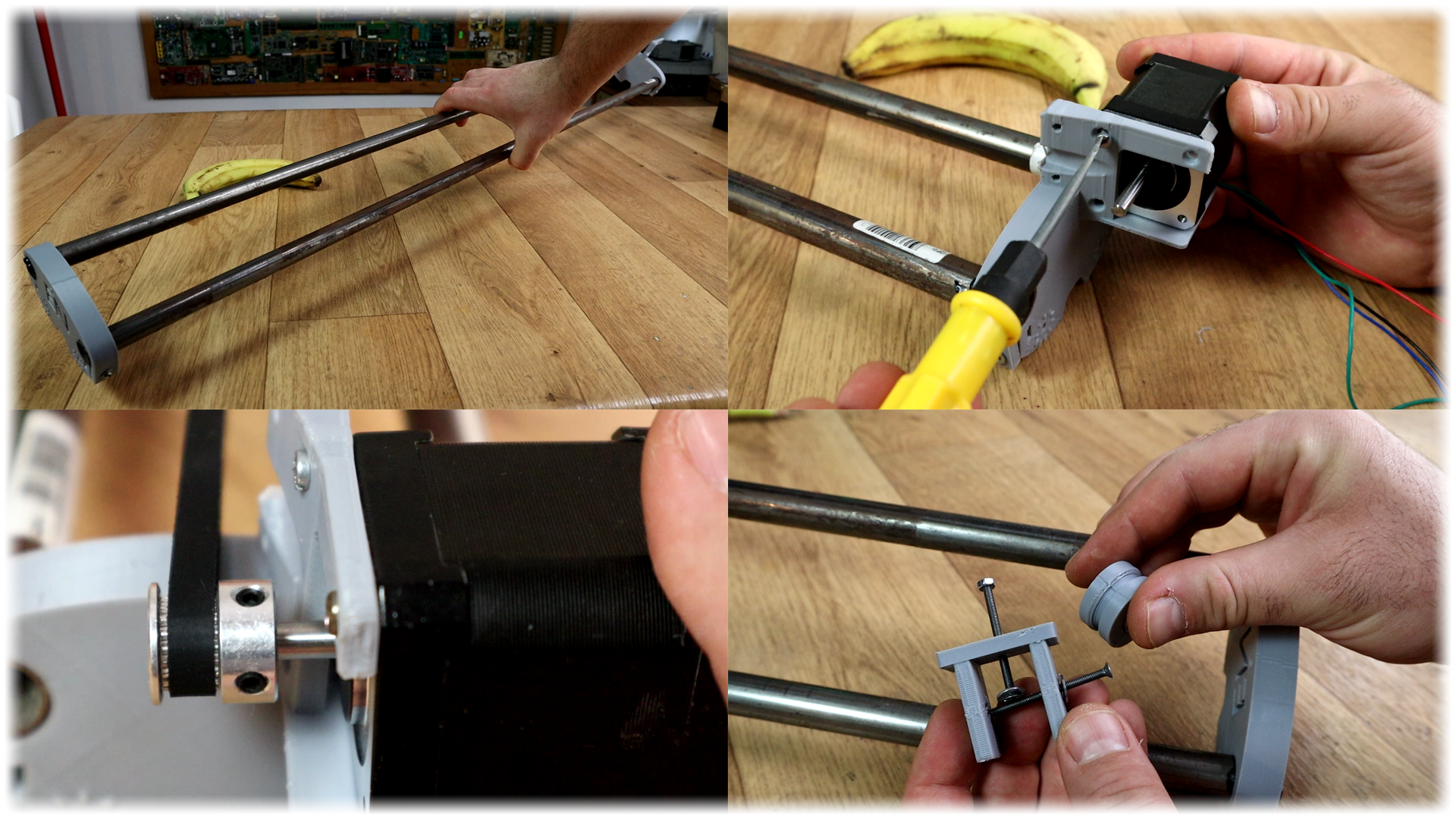
I mount the side parts and the two metal tubes. For the slider, I’ve used some bearings that I’ve got out from old rollers. You could use normal 22mm diameter bearings with a screw nut in between like in the photo below so the two bearings would fit on the metal bar with a gap in between. I’ve screwed in place the 4 pairs of bearings on the slider plate and then add two more pairs of rollers on the middle holes so the plate won’t be able to get out.
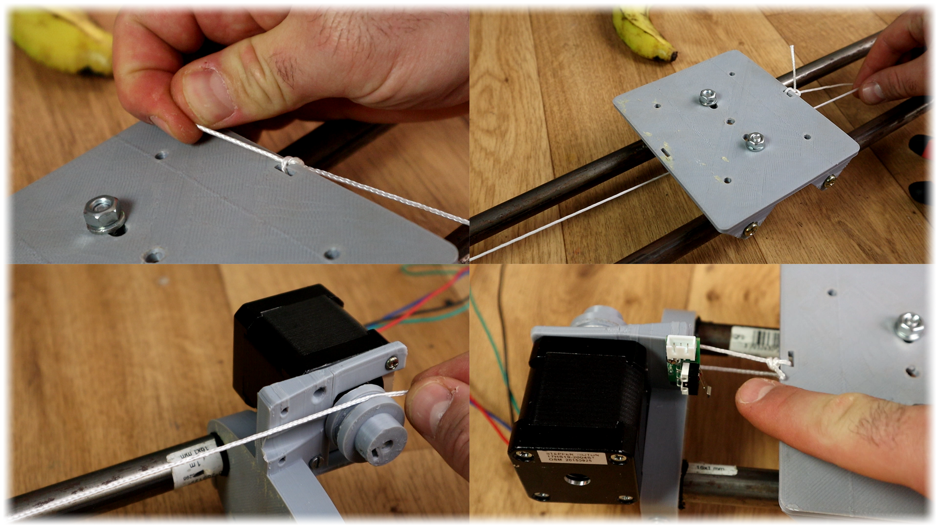
Now I screw in place the step motor on the left support. To transfer movement you should use timing belt and a pully. But, the one I’ve ordered is not long enough so till I receive a new one, I’ll just use some kind of wire. I’ve printed a special pulley that could get screwed on the shaft of the motor, and another one on the other side with a small bearing inside. Now I tie one end of the wire to the rolling plate, pass the wire over the pully and then over the bearing at the other end and finally tie it on the other side of the rolling plate.
Finally, I add an end stop switch like this one on the motor side support. This switch will be used to home the position of the slider each time that you want. That’s it, the slider body is ready. The wire of the motor and the switch will go inside the control case. Now let’s prepare the case.
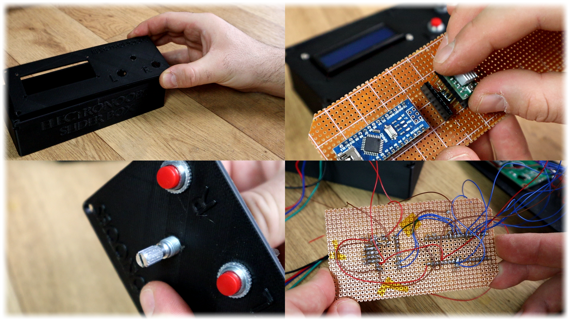
Download and follow the schematic of the project from a link below. I screw in place the LCD, the two push buttons and the rotary encoder in the middle. On a drilled PCB and using female pins I solder an Arduino NANO and the step motor driver together with a 10uF capacitor. I also solder 4 pins at the driver output for the step motor connector.
Now, using wires I connect the i2c pins of the LCD to pins A4 and A5 of the Arduino. The rotary encoder has two outputs and we name those data and clock and they will be connected to pins 8 and 9 of the Arduino. The rotary also has a push button inside and it will be connected to digital pin 10. The other two push buttons are connected to pins 11 and 12 and the end stop switch to digital pin 4.