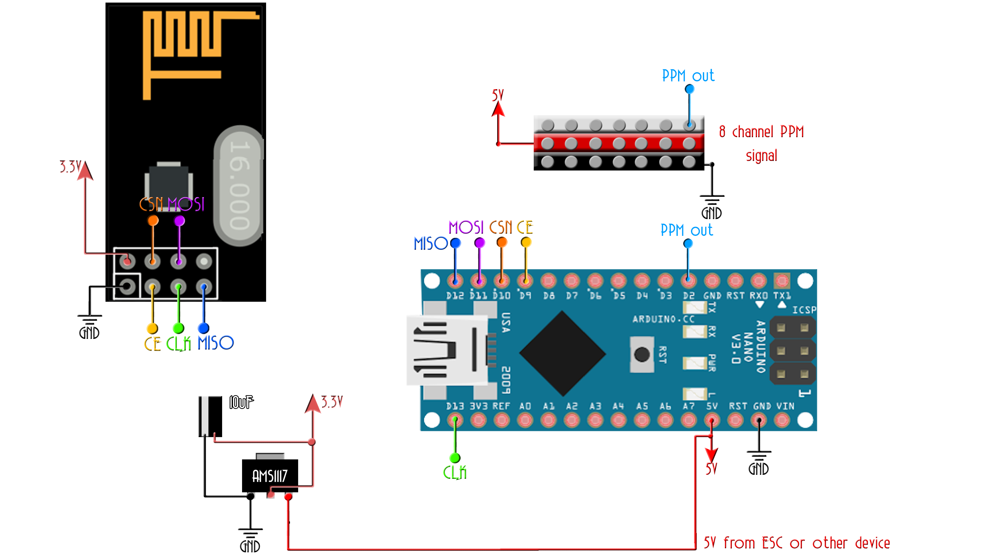
This code is for the schematic.
/* Receiver code for the Arduino Radio control with PWM output
 * Install the NRF24 library to your IDE
 * Upload this code to the Arduino UNO, NANO, Pro mini (5V,16MHz)
 * Connect a NRF24 module to it:

    Module // Arduino UNO,NANO

    GND    ->   GND
    Vcc    ->   3.3V
    CE     ->   D9
    CSN    ->   D10
    CLK    ->   D13
    MOSI   ->   D11
    MISO   ->   D12

This code receive 7 channels and create a PPM output on digital D2 with all the values
Please, like share and subscribe : https://www.youtube.com/c/ELECTRONOOBS
*/


#include <SPI.h>
#include <nRF24L01.h>
#include <RF24.h>


////////////////////// PPM CONFIGURATION//////////////////////////
#define channel_number 7  //set the number of channels, in this case: 4 channels
#define sigPin 2          //set PPM signal output pin on the arduino
#define PPM_FrLen 27000   //set the PPM frame length in microseconds (1ms = 1000µs)
#define PPM_PulseLen 400  //set the pulse length
//////////////////////////////////////////////////////////////////

int ppm[channel_number];

const uint64_t My_radio_pipeIn = 0xE8E8F0F0E1LL;     //Remember that this code is the same as in the transmitter
RF24 radio(9, 10);  //CSN and CE pins

// The sizeof this struct should not exceed 32 bytes
struct Received_data {
  byte ch1;
  byte ch2;
  byte ch3;
  byte ch4;
  byte ch5;
  byte ch6;
  byte ch7;
};

Received_data received_data;


void reset_received_Data()
{
  // 'safe' values to use when NO radio input is detected
  received_data.ch1 = 0;      //Throttle (channel 1) to 0
  received_data.ch2 = 127;
  received_data.ch3 = 127;
  received_data.ch4 = 127;
  received_data.ch5 = 0;
  received_data.ch6 = 0;
  received_data.ch7 = 0;

  PPM_width_Values();
}

void PPM_width_Values()
{
  //Here we map the received values from 1000 to 2000
  //and create the ppm signals for each channel
  ppm[0] = map(received_data.ch1,   0, 255, 1000, 2000);
  ppm[1] = map(received_data.ch2,   0, 255, 1000, 2000);
  ppm[2] = map(received_data.ch3,   0, 255, 1000, 2000);
  ppm[3] = map(received_data.ch4,   0, 255, 1000, 2000);
  ppm[4] = map(received_data.ch5,   0, 1, 1000, 2000);
  ppm[5] = map(received_data.ch6,   0, 1, 1000, 2000);
  ppm[6] = map(received_data.ch7,   0, 255, 1000, 2000);
  }

/**************************************************/


/**************************************************/

void setup()
{
  pinMode(sigPin, OUTPUT);
  digitalWrite(sigPin, 0);  //set the PPM (D2 in this case) signal pin to the default state (off)

  //Configure the interruption registers that will create the PPM signal
  cli();
  TCCR1A = 0; // set entire TCCR1 register to 0
  TCCR1B = 0;

  OCR1A = 100;  // compare match register (not very important, sets the timeout for the first interrupt)
  TCCR1B |= (1 << WGM12);  // turn on CTC mode
  TCCR1B |= (1 << CS11);  // 8 prescaler: 0,5 microseconds at 16mhz
  TIMSK1 |= (1 << OCIE1A); // enable timer compare interrupt
  sei();

  //Call the reset data function
  reset_received_Data();

  //Once again, begin and radio configuration
  radio.begin();
  radio.setAutoAck(false);
  radio.setDataRate(RF24_250KBPS);
  radio.openReadingPipe(1,My_radio_pipeIn);

  //We start the radio comunication
  radio.startListening();

}

/**************************************************/

unsigned long lastRecvTime = 0;

//We create the function that will read the data each certain time
void receive_the_data()
{
  while ( radio.available() ) {
  radio.read(&received_data, sizeof(Received_data));
  lastRecvTime = millis(); //Here we receive the data
}
}

/**************************************************/


void loop()
{
  //Receive the radio data
  receive_the_data();
  //Create the PPM widths
  PPM_width_Values();

  //////////This small if will reset the data if signal is lost for 1 sec.
/////////////////////////////////////////////////////////////////////////
  unsigned long now = millis();
  if ( now - lastRecvTime > 1000 ) {
    // signal lost?
    reset_received_Data();
    //Go up and change the initial values if you want depending on
    //your aplications. Put 0 for throttle in case of drones so it won't
    //fly away
  }
}//Loop end


//#error Delete this line befor you cahnge the value (clockMultiplier) below
#define clockMultiplier 2 // set this to 2 if you are using a 16MHz arduino, leave as 1 for an 8MHz arduino


//Interruption vector. here we create the PPM signal
ISR(TIMER1_COMPA_vect){
  static boolean state = true;

  TCNT1 = 0;

  if ( state ) {
    //end pulse
    PORTD = PORTD & ~B00000100; // turn pin 2 off. Could also use: digitalWrite(sigPin,0)
    OCR1A = PPM_PulseLen * clockMultiplier;
    state = false;
  }
  else {
    //start pulse
    static byte cur_chan_numb;
    static unsigned int calc_rest;

    PORTD = PORTD | B00000100; // turn pin 2 on. Could also use: digitalWrite(sigPin,1)
    state = true;

    if(cur_chan_numb >= channel_number) {
      cur_chan_numb = 0;
      calc_rest += PPM_PulseLen;
      OCR1A = (PPM_FrLen - calc_rest) * clockMultiplier;
      calc_rest = 0;
    }
    else {
      OCR1A = (ppm[cur_chan_numb] - PPM_PulseLen) * clockMultiplier;
      calc_rest += ppm[cur_chan_numb];
      cur_chan_numb++;
    }
  }
}