This code is for the schematic. I know that the code is quite long but read it line by line. Is not that difficult. Keep up you guys!
/* Max6675 Module ==> Arduino
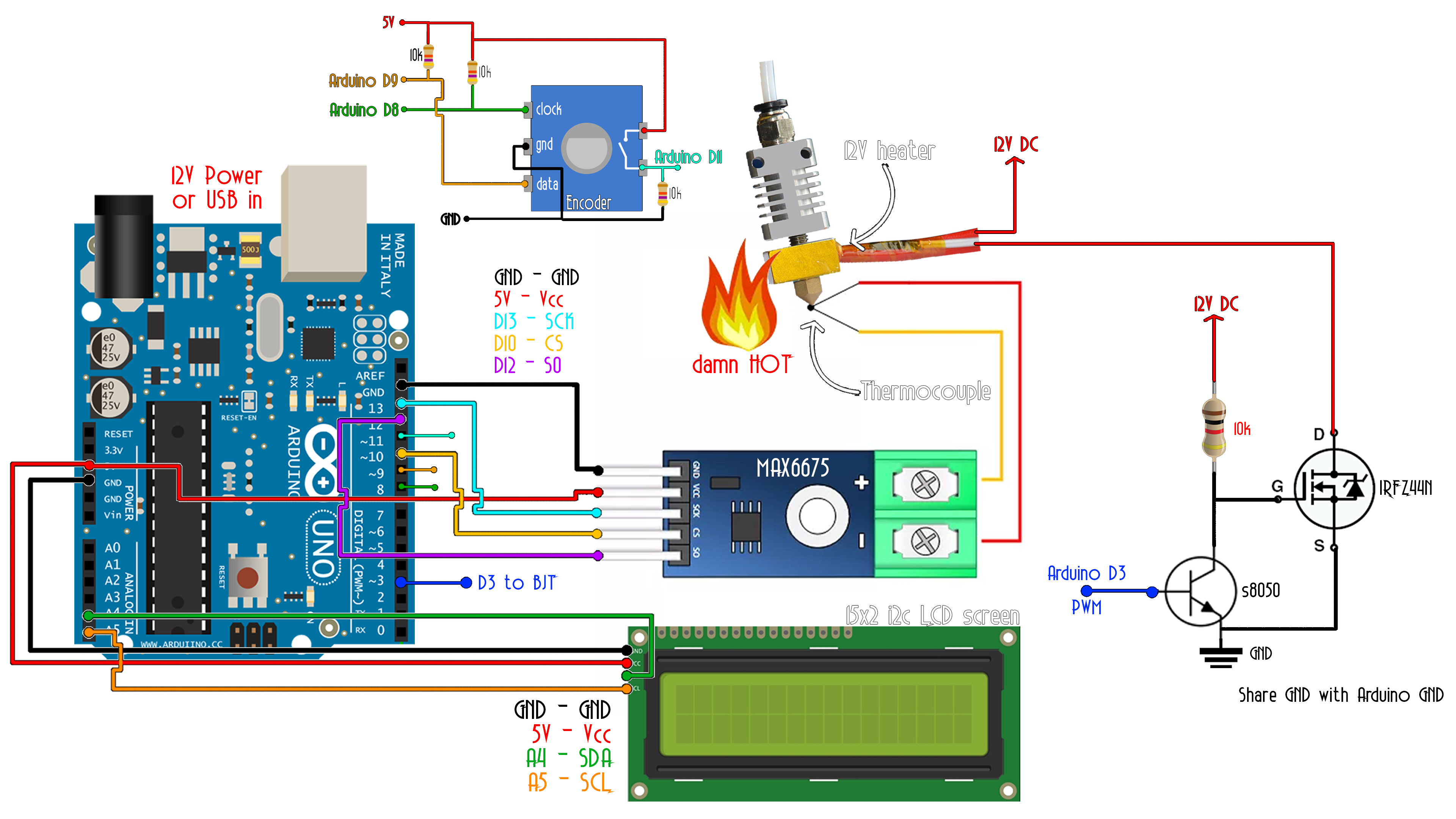
* CS ==> D10
* SO ==> D12
* SCK ==> D13
* Vcc ==> Vcc (5v)
* Gnd ==> Gnd */
#include <SPI.h>
//LCD config
#include <Wire.h>
#include <LiquidCrystal_I2C.h>
LiquidCrystal_I2C lcd(0x3f,20,4); //sometimes the adress is not 0x3f. Change to 0x27 if it dosn't work.
/* i2c LCD Module ==> Arduino
* SCL ==> A5
* SDA ==> A4
* Vcc ==> Vcc (5v)
* Gnd ==> Gnd */
//I/O
int PWM_pin = 3; //Pin for PWM signal to the MOSFET driver (the BJT npn with pullup)
int clk = 8; //Pin 1 from rotary encoder
int data = 9; //Pin 2 from rotary encoder
//Variables
float set_temperature = 0; //Default temperature setpoint. Leave it 0 and control it with rotary encoder
float temperature_read = 0.0;
float PID_error = 0;
float previous_error = 0;
float elapsedTime, Time, timePrev;
float PID_value = 0;
int button_pressed = 0;
int menu_activated=0;
float last_set_temperature = 0;
//Vraiables for rotary encoder state detection
int clk_State;
int Last_State;
bool dt_State;
//PID constants
//////////////////////////////////////////////////////////
int kp = 90; int ki = 30; int kd = 80;
//////////////////////////////////////////////////////////
int PID_p = 0; int PID_i = 0; int PID_d = 0;
float last_kp = 0;
float last_ki = 0;
float last_kd = 0;
int PID_values_fixed =0;
//Pins for the SPI with MAX6675
#define MAX6675_CS 10
#define MAX6675_SO 12
#define MAX6675_SCK 13
void setup() {
pinMode(PWM_pin,OUTPUT);
TCCR2B = TCCR2B & B11111000 | 0x03; // pin 3 and 11 PWM frequency of 928.5 Hz
Time = millis();
Last_State = (PINB & B00000001); //Detect first state of the encoder
PCICR |= (1 << PCIE0); //enable PCMSK0 scan
PCMSK0 |= (1 << PCINT0); //Set pin D8 trigger an interrupt on state change.
PCMSK0 |= (1 << PCINT1); //Set pin D9 trigger an interrupt on state change.
PCMSK0 |= (1 << PCINT3); //Set pin D11 trigger an interrupt on state change.
pinMode(11,INPUT);
pinMode(9,INPUT);
pinMode(8,INPUT);
lcd.init();
lcd.backlight();
}
void loop() {
if(menu_activated==0)
{
// First we read the real value of temperature
temperature_read = readThermocouple();
//Next we calculate the error between the setpoint and the real value
PID_error = set_temperature - temperature_read + 3;
//Calculate the P value
PID_p = 0.01*kp * PID_error;
//Calculate the I value in a range on +-3
PID_i = 0.01*PID_i + (ki * PID_error);
//For derivative we need real time to calculate speed change rate
timePrev = Time; // the previous time is stored before the actual time read
Time = millis(); // actual time read
elapsedTime = (Time - timePrev) / 1000;
//Now we can calculate the D calue
PID_d = 0.01*kd*((PID_error - previous_error)/elapsedTime);
//Final total PID value is the sum of P + I + D
PID_value = PID_p + PID_i + PID_d;
//We define PWM range between 0 and 255
if(PID_value < 0)
{ PID_value = 0; }
if(PID_value > 255)
{ PID_value = 255; }
//Now we can write the PWM signal to the mosfet on digital pin D3
//Since we activate the MOSFET with a 0 to the base of the BJT, we write 255-PID value (inverted)
analogWrite(PWM_pin,255-PID_value);
previous_error = PID_error; //Remember to store the previous error for next loop.
delay(250); //Refresh rate + delay of LCD print
//lcd.clear();
lcd.setCursor(0,0);
lcd.print("PID TEMP control");
lcd.setCursor(0,1);
lcd.print("S:");
lcd.setCursor(2,1);
lcd.print(set_temperature,1);
lcd.setCursor(9,1);
lcd.print("R:");
lcd.setCursor(11,1);
lcd.print(temperature_read,1);
}//end of menu 0 (PID control)
//First page of menu (temp setpoint)
if(menu_activated == 1)
{
analogWrite(PWM_pin,255);
if(set_temperature != last_set_temperature)
{
lcd.clear();
lcd.setCursor(0,0);
lcd.print("Set temperature");
lcd.setCursor(0,1);
lcd.print(set_temperature);
}
last_set_temperature = set_temperature;
}//end of menu 1
//Second page of menu (P set)
if(menu_activated == 2)
{
if(kp != last_kp)
{
lcd.clear();
lcd.setCursor(0,0);
lcd.print("Set P value ");
lcd.setCursor(0,1);
lcd.print(kp);
}
last_kp = kp;
}//end of menu 2
//Third page of menu (I set)
if(menu_activated == 3)
{
if(ki != last_ki)
{
lcd.clear();
lcd.setCursor(0,0);
lcd.print("Set I value ");
lcd.setCursor(0,1);
lcd.print(ki);
}
last_ki = ki;
}//end of menu 3
//Forth page of menu (D set)
if(menu_activated == 4)
{
if(kd != last_kd)
{
lcd.clear();
lcd.setCursor(0,0);
lcd.print("Set D value ");
lcd.setCursor(0,1);
lcd.print(kd);
}
last_kd = kd;
}//end of menu 4
}//Loop end
//The function that reads the SPI data from MAX6675
double readThermocouple() {
uint16_t v;
pinMode(MAX6675_CS, OUTPUT);
pinMode(MAX6675_SO, INPUT);
pinMode(MAX6675_SCK, OUTPUT);
digitalWrite(MAX6675_CS, LOW);
delay(1);
// Read in 16 bits,
// 15 = 0 always
// 14..2 = 0.25 degree counts MSB First
// 2 = 1 if thermocouple is open circuit
// 1..0 = uninteresting status
v = shiftIn(MAX6675_SO, MAX6675_SCK, MSBFIRST);
v <<= 8;
v |= shiftIn(MAX6675_SO, MAX6675_SCK, MSBFIRST);
digitalWrite(MAX6675_CS, HIGH);
if (v & 0x4)
{
// Bit 2 indicates if the thermocouple is disconnected
return NAN;
}
// The lower three bits (0,1,2) are discarded status bits
v >>= 3;
// The remaining bits are the number of 0.25 degree (C) counts
return v*0.25;
}
//The interruption vector for push button and rotary encoder
ISR(PCINT0_vect){
if(menu_activated==1)
{
clk_State = (PINB & B00000001); //pin 8 state? It is HIGH?
dt_State = (PINB & B00000010);
if (clk_State != Last_State){
// If the data state is different to the clock state, that means the encoder is rotating clockwise
if (dt_State != clk_State) {
set_temperature = set_temperature+0.5 ;
}
else {
set_temperature = set_temperature-0.5;
}
}
Last_State = clk_State; // Updates the previous state of the clock with the current state
}
if(menu_activated==2)
{
clk_State = (PINB & B00000001); //pin 8 state?
dt_State = (PINB & B00000010);
if (clk_State != Last_State){
// If the data state is different to the clock state, that means the encoder is rotating clockwise
if (dt_State != clk_State) {
kp = kp+1 ;
}
else {
kp = kp-1;
}
}
Last_State = clk_State; // Updates the previous state of the clock with the current state
}
if(menu_activated==3)
{
clk_State = (PINB & B00000001); //pin 8 state?
dt_State = (PINB & B00000010);
if (clk_State != Last_State){
// If the data state is different to the clock state, that means the encoder is rotating clockwise
if (dt_State != clk_State) {
ki = ki+1 ;
}
else {
ki = ki-1;
}
}
Last_State = clk_State; // Updates the previous state of the clock with the current state
}
if(menu_activated==4)
{
clk_State = (PINB & B00000001); //pin 8 state?
dt_State = (PINB & B00000010);
if (clk_State != Last_State){
// If the data state is different to the clock state, that means the encoder is rotating clockwise
if (dt_State != clk_State) {
kd = kd+1 ;
}
else {
kd = kd-1;
}
}
Last_State = clk_State; // Updates the previous state of the clock with the current state
}
//Push button was pressed!
if (PINB & B00001000) //Pin D11 is HIGH?
{
button_pressed = 1;
}
//We navigate through the 4 menus with each button pressed
else if(button_pressed == 1)
{
if(menu_activated==4)
{
menu_activated = 0;
PID_values_fixed=1;
button_pressed=0;
delay(1000);
}
if(menu_activated==3)
{
menu_activated = menu_activated + 1;
button_pressed=0;
kd = kd + 1;
delay(1000);
}
if(menu_activated==2)
{
menu_activated = menu_activated + 1;
button_pressed=0;
ki = ki + 1;
delay(1000);
}
if(menu_activated==1)
{
menu_activated = menu_activated + 1;
button_pressed=0;
kp = kp + 1;
delay(1000);
}
if(menu_activated==0 && PID_values_fixed != 1)
{
menu_activated = menu_activated + 1;
button_pressed=0;
set_temperature = set_temperature+1;
delay(1000);
}
PID_values_fixed = 0;
}
}