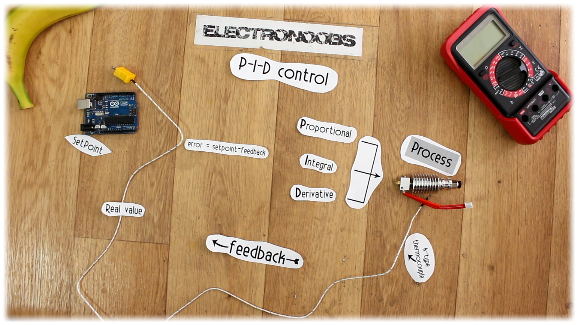

What’s up my friends, welcome back. What I want, is the aluminum block below to have let’s say, exactly 100 degrees. I’ll control the real temperature using a K type thermocouple. To read the data I'll use the MAX66 75 breakout module and control the PID algorithm with and Arduino. Finally, to apply power we will make a small circuit using a MOSFET or maybe a TRIAC in case of high AC voltages. This will be a close loop. The thermocouple measures the real values, the Arduino creates the signal applied to the MOSFET and this transistor will control the power of a heating element inside of the aluminum block and once again the thermocouple will measure the value, that’s why it’s a close loop.

So, the first thing is to understand how a PID temperature controller will work. As in any PID system we need to define a final process, in our case will be the final temperature that we will achieve. In order to control this temperature, we will need a feedback. So, any PID control will have some sort of feedback. In our case, that feedback is made using a K type thermocouple that will measure the real temperature of the system.
This type of control will also need a setpoint, which in our case is the desired temperature. The system will make the difference between the desired value and the feedback from the output (error), and using 3 constants, the proportional, the integral and derivative, we can change the output according to the feedback.

So, if we want the heating block to have exactly 100 degrees what we will do first is apply power to it. This will start heating up. By the time it reaches the setpoint value, which in this case is 100 degrees, the feedback will inform that to the PID control and this will start lowering the power applied to the heating element, and in our example that will be made using a PWM signal applied to a MOSFET that will control the voltage that goes to the heating element inside the block.
So, it is obvious, if the real temperature is higher than the setpoint, we lower the power value, if the real temperature is lower than the setpoint, well, we increase the power till it reaches the desired value.

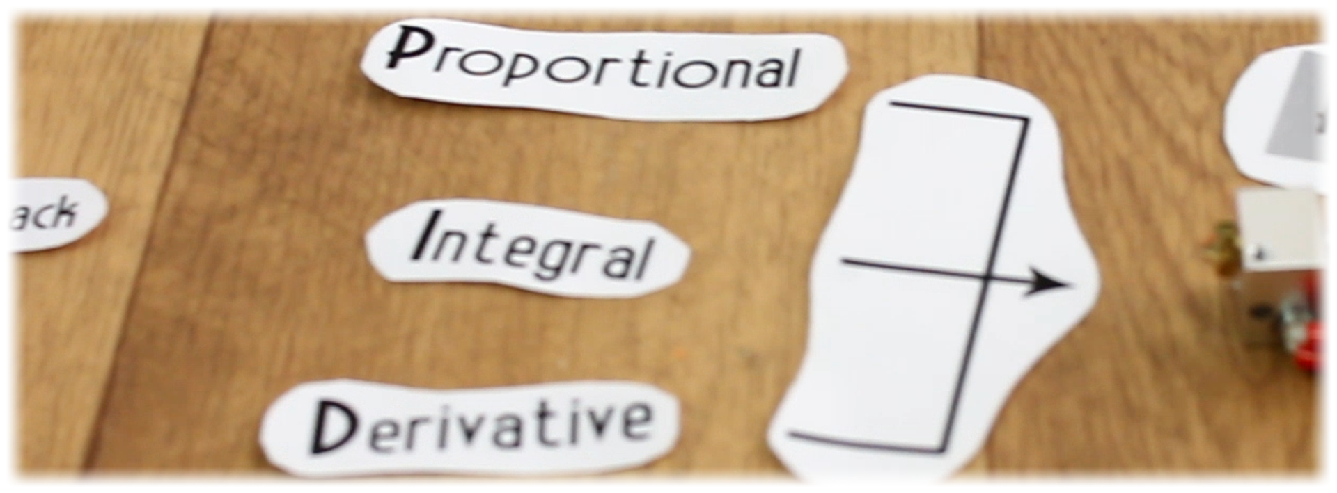
If we do just that, that is called P control, or proportional control, and will end up in a temperature oscillation between certain values and it will very difficult or never be stable. For that we add the D control, or derivative. This kind of control will react to the speed of temperature change. So, if, for example, if we blow air on the aluminum block, the derivative will fast push the power to maximum in order to keep the temperature. Finally, we have the I, or integral. This will sum the error on each loop getting bigger and bigger with each loop, or, in case of negative error, getting lower and lower. The sum of all these parts, the P, the I and D, makes a PID control. It’s our job to find the correct constants for each of this PID elements.
So, let’s start building this project. The first thing we will do, is see how to read the real temperature. Below we can see a K type thermocouple, and the MAX 66 75 breakout module. This will amplify and compensate the voltage created by the thermocouple. It has an SPI communication so we'll have to connect these pins to the Arduino SPI port.

Use the connections below and let’s test it out. On a breadboard I connect the MAX 66 75 and the thermocouple. Be careful, the thermocouple has polarity so connect positive to positive and negative to negative. Connect the SPI pins to the Arduino and also supply 5V and GND.
Now upload the next code to the Arduino UNO/NANO. This code will just read the SPI data from the module using a function called "readThermocouple" and that gives us the real temperature. We print the value on the LCD screen. Have in mind that if you don't have the LiquidCrystal_I2C library, you'll have to dwonload it and install it to the Arduino IDE. I heat the thermocouple with a lighter and there you go, I have the real value on the LCD screen.
/*    Max6675 Module  ==>   Arduino
 *    CS              ==>     D10
 *    SO              ==>     D12
 *    SCK             ==>     D13
 *    Vcc             ==>     Vcc (5v)
 *    Gnd             ==>     Gnd      */

//LCD config
#include <Wire.h>
#include <LiquidCrystal_I2C.h>    //If you don't have the LiquidCrystal_I2C library, download it and install it
LiquidCrystal_I2C lcd(0x3f,20,4);  //sometimes the adress is not 0x3f. Change to 0x27 if it dosn't work.

/*    i2c LCD Module  ==>   Arduino
 *    SCL             ==>     A5
 *    SDA             ==>     A4
 *    Vcc             ==>     Vcc (5v)
 *    Gnd             ==>     Gnd      */

#include <SPI.h>

#define MAX6675_CS   10
#define MAX6675_SO   12
#define MAX6675_SCK  13

void setup() {
  lcd.init();
  lcd.backlight();
}

void loop() {
  float temperature_read = readThermocouple();
  lcd.setCursor(0,0);
  lcd.print("TEMPERATURE");
  lcd.setCursor(7,1);
  lcd.print(temperature_read,1);
  delay(300);
}


double readThermocouple() {

  uint16_t v;
  pinMode(MAX6675_CS, OUTPUT);
  pinMode(MAX6675_SO, INPUT);
  pinMode(MAX6675_SCK, OUTPUT);

  digitalWrite(MAX6675_CS, LOW);
  delay(1);

  // Read in 16 bits,
  //  15    = 0 always
  //  14..2 = 0.25 degree counts MSB First
  //  2     = 1 if thermocouple is open circuit
  //  1..0  = uninteresting status

  v = shiftIn(MAX6675_SO, MAX6675_SCK, MSBFIRST);
  v <<= 8;
  v |= shiftIn(MAX6675_SO, MAX6675_SCK, MSBFIRST);

  digitalWrite(MAX6675_CS, HIGH);
  if (v & 0x4)
  {
    // Bit 2 indicates if the thermocouple is disconnected
    return NAN;
  }

  // The lower three bits (0,1,2) are discarded status bits
  v >>= 3;

  // The remaining bits are the number of 0.25 degree (C) counts
  return v*0.25;
}
