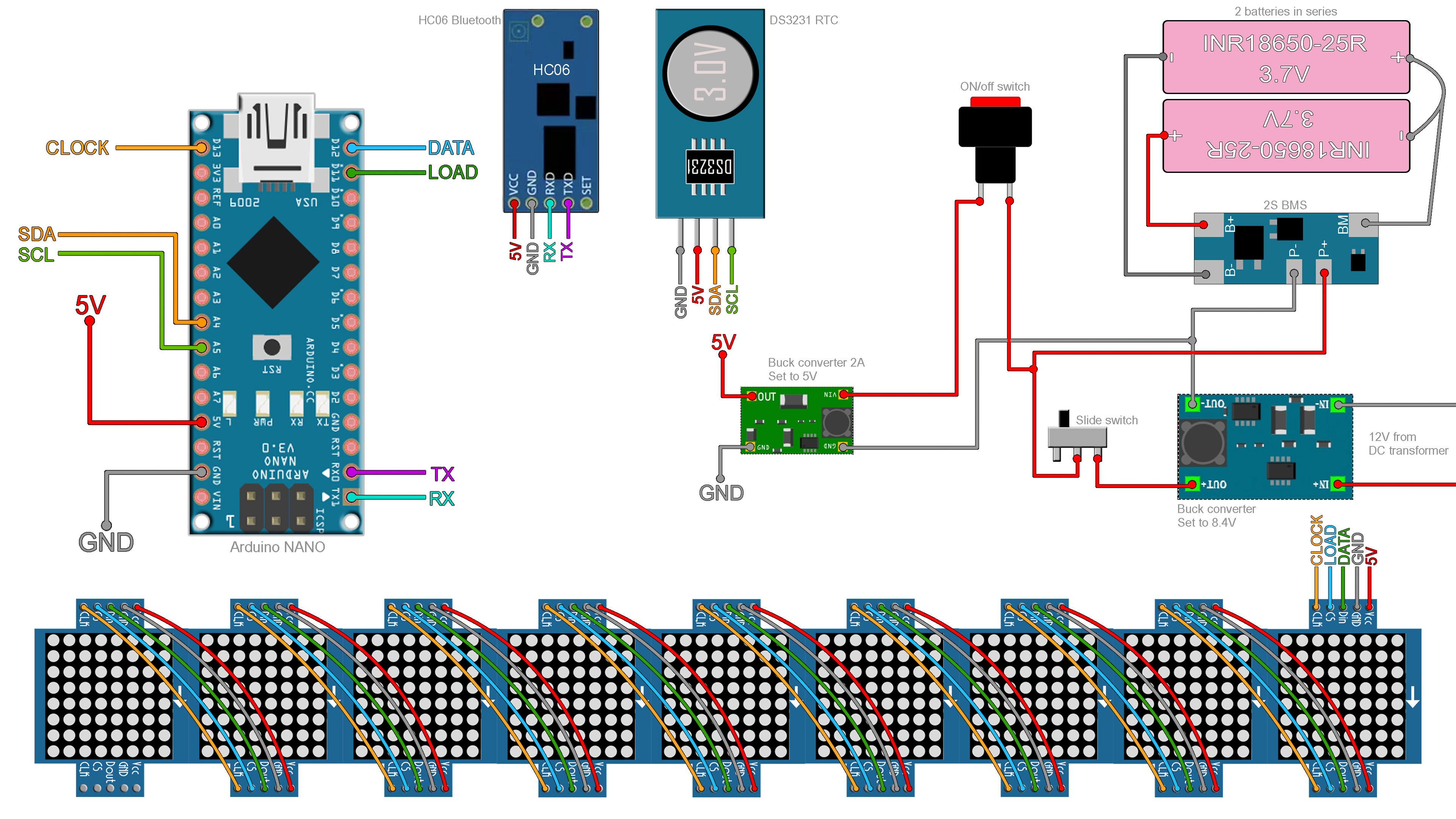
The schematic has a few connections. Let's start from the power part. To charge the betteries we need to give exactly 8.4V to the BMS board. So, from the 12V DC trasnformer jack, connect the buck converter and set it to 8.4V. Then add a sliding switch to separate the circuits. Connect the BMS mdoule to the 2 batteries in series. Then at the output add the on and off switch and at the output of this switch add another small buck converter and set this one to 5V. The Arduino has a voltage regulator but is not powerful enough. Then connect the RTC module to the Arduino. The Bluetooth module uses the RX and TX pins. So make sure you upload the code before you connect the module, otherwise the code won't uplaod. We can't have anything connected to the TX and RX pins when we uplaod the code. Go below, downlaod it and uplaod it. Then connect the Bluetooth module and the dot matrices in series as in the schematic below.