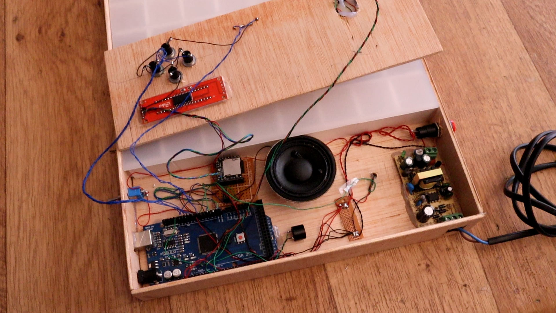
Today we will see how to build this awesome TETRIS game made with arduino. The project also has sounds as for example the tetris theme and other beeps and you could add any other sound to the SD card inside the DFplayer module. To create the matrix I've used the well known WS2812 LED addressable strip with RGB LEDs. So with only 1 wire we could control all LEDs and all colors. The code I've used is based on this original file from MarginallyCleve on GitHub. But I've placed new parts such as two 7 segments modules to print the score and top score. And not just that, the top score is saved to the EEPROM memory so it will stay there always. Now we could put the game on pause as well and play sounds. Let's see what we need and how to make this project.
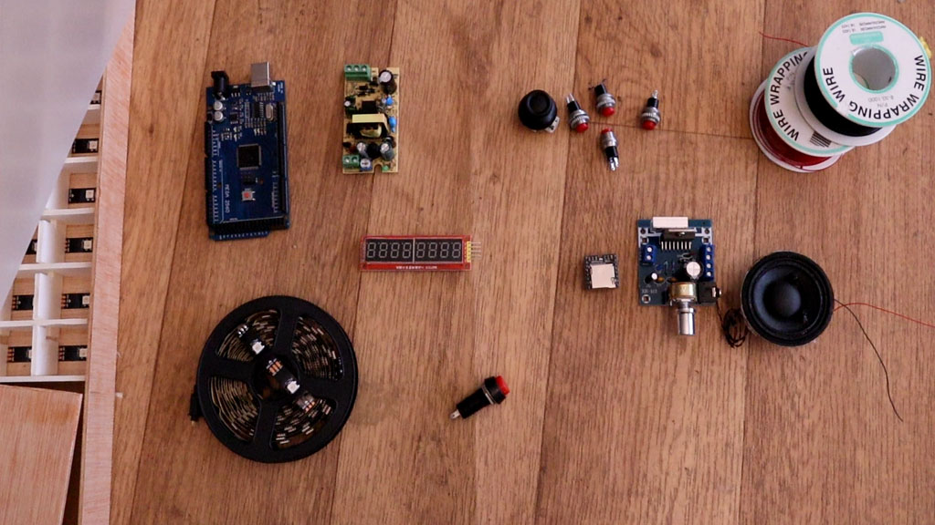
For this project we need a few components. See full list here on this link. But anyway, make sure you will use an Arduino MEGA because the UNO don't have enough memory for this project. Then get that serial controlled 7 segments display module with 8 digits. The DF player and a SD micro card of 4 or below 4Gb. Get the WS2812 LED strip, the one with 30 LEDs per meter and get 5m so 150 LEDs because we need 128. You'll need a power supply of 5V and at least 2 amps of current. You could also buy an amplifier and place that between the DFplayer nand the speaker. See all parts on the full part list.
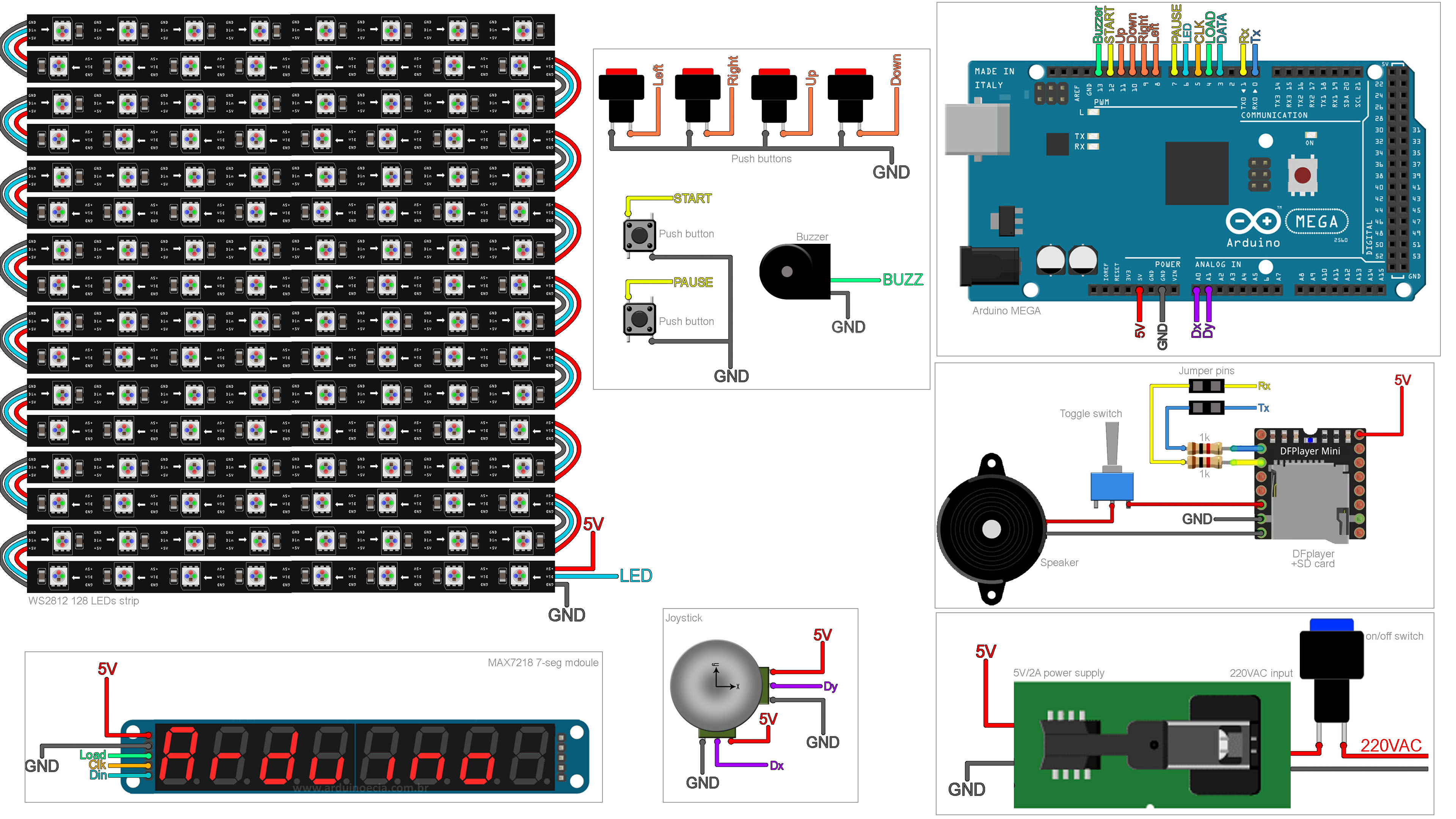
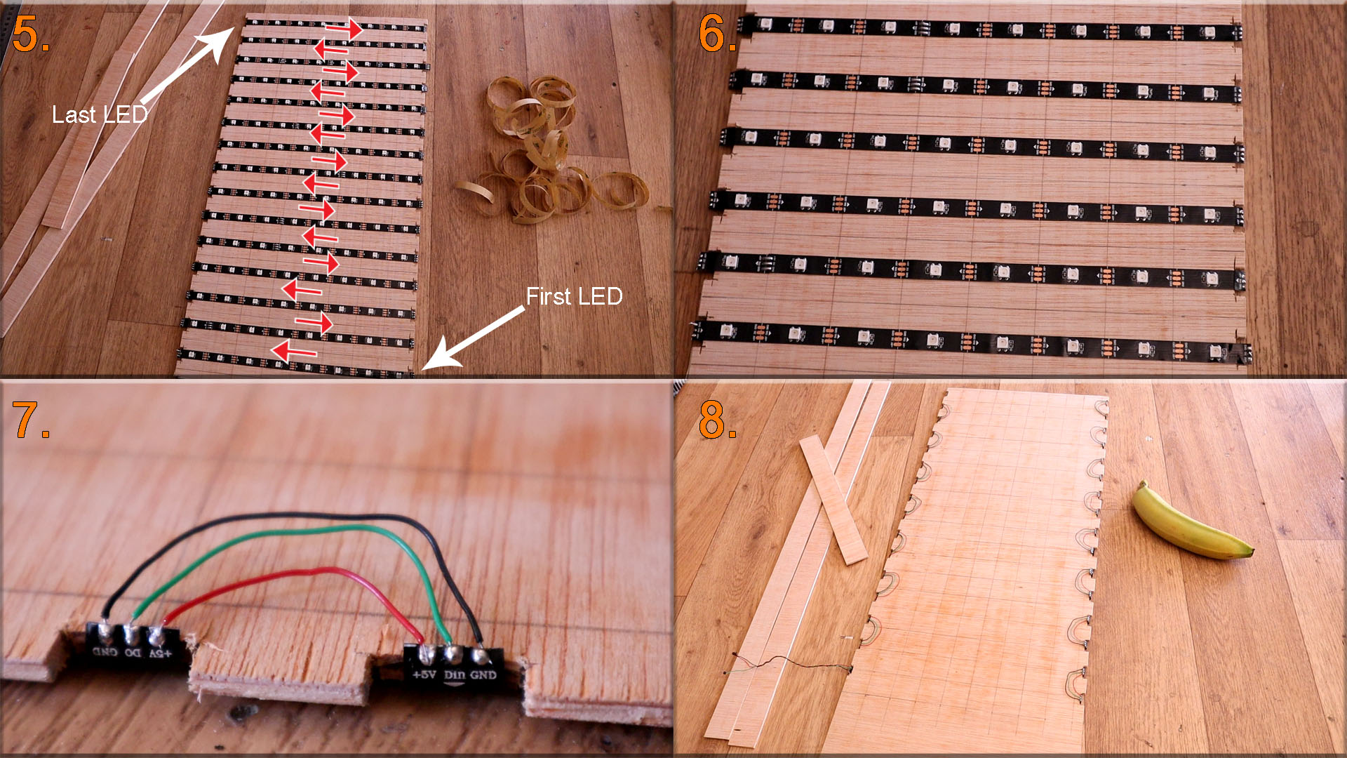
The schematic has a few connections. We start with the power supply connected to 220VAC with an on and off switch and that will give us 5V. These 5V are connected to all the modules, the Arduino and the LED strip. Then, for the DFplayer make sure you add some jumper pins in order to disconnect the TX and RX pins in case that the code upload will give us problems. Add the 1k resistors to eliminate noise and a toggle switch between the speaker and the DFplayer. Each button is connected to GND and the other side of the button to one input of the Arduino. We don't need external pullup resistors since all these inputs will be defined as PULLUP in the code. Connect power and the serial wires to the 7 segments display and finally connect 5V, GND and the LED wire to the WS2812 strip. When you make the LEDs matrix, look that the arrow on the strip will go in the correct dirrection.
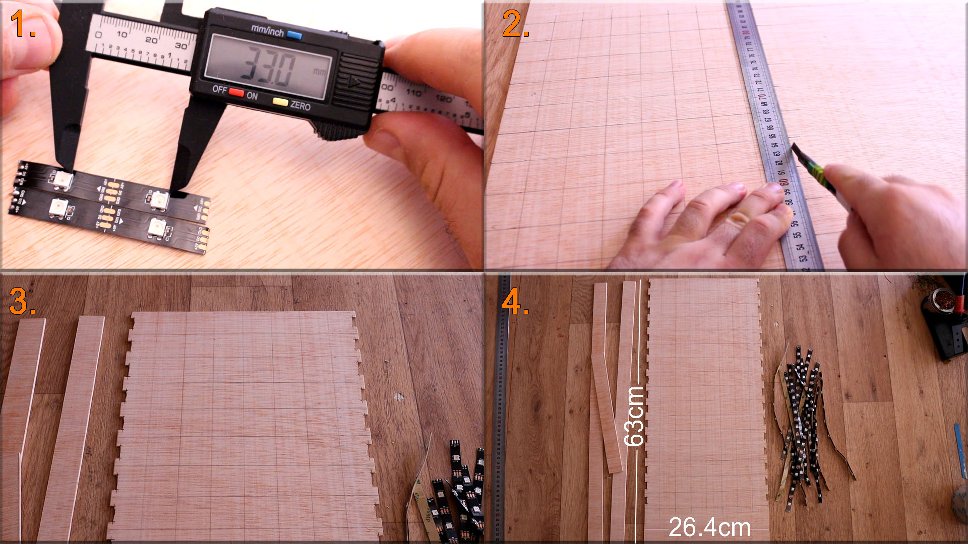
First, we need to know the distance between LEDs, in this case 33mm as you can see below on "1". I draw 8 vertical lines and 16 horizaontal lines on a piece of plywood and with 33mm separation in between. Then I use my cutter to cut the main part as you can see on "2". This part will be 26.4cm wide for 8 columns of LEDs. The length of the baord will be 52.8cm for 16 rows of LEDs and 10cm more for the electronics on the bottom so a total length of 63cm. We also need two sides of 63cm long and 4cm width and another 2 parts for the top and bottom parts of the case of 26.4cm long and 4cm width. Now, as you can see on "3" on each row we have a bit of the plywood cut out. That small hole is for the LED strip to be able to pass the wires on the other side. So, cutt 16 holes on one side and 16 more on the other for all 16 rows. Finally, on "4" we have the wood parts prepaired, so get the WS2812 LED strip and cut out 16 strips of 8 LEDs each.
Ok, now we can remove the protective part on the abck of the LED stripes and glue them in the middle of each row on the plywood.
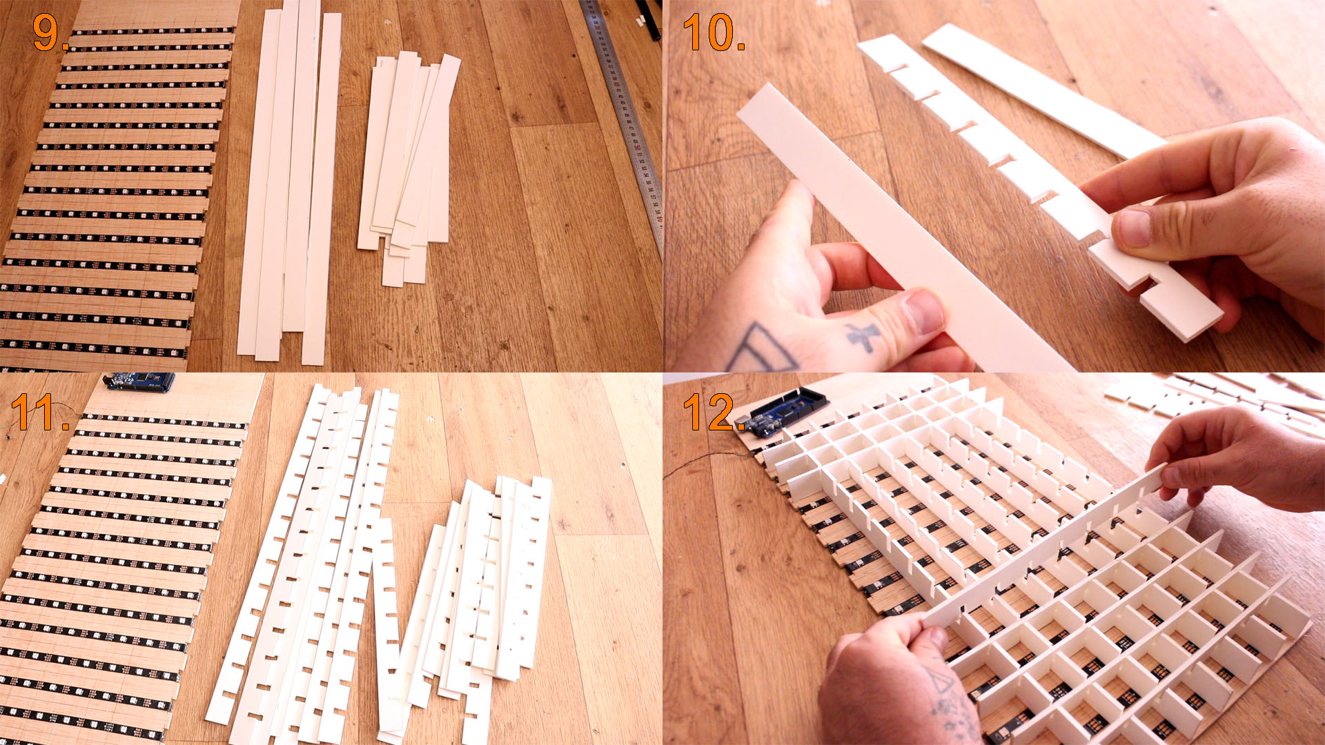
This is the long and boring part. We need to make the spacers and create some sort of grid to separate the light from one LED from the other LEDs around and avoid color blend and also give a squared shape instead of a spot shape. For that I'll use some RC modeling foam like the one you can see below. It is easy to cut and is whiteso it will reflect light. We need to cut 7 long strips of 52.8cm and 3mm width then 15 short ones of 26.6cm long and 3cm width. But the long part is to cut a hole for each row and column, so a total of 105 holes as you can see on "10". We will use these holes to join together each foam strip and create a grid as you can see on "11". So first place the long ones with the holes upwards. Then add all the rows with the hole downwards and complete the grid. Finally you could add a bit of glue to fix the grid exactly on top of the lines we have on the plywood.
At this point "13" we have the grid so we could test how it works. But the light must hit an opaque surface in order to see it better. So, first as you can see on "14" I glue the sides of the case and then we cut a piece of white-transparend acrylic. This must have the width of the case but the length only to cover the grid. I cut taht part and place it on top of the grid and the difference is huge.
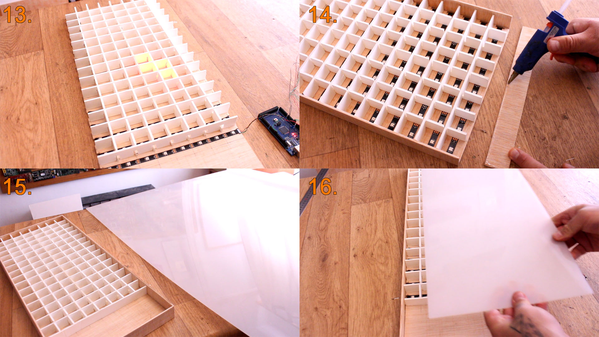
As you can see below the light with the acrylic on top is better. The camera makes a glow effect, but trust me, with the acrylic you will see the light a lot better and also the case will look nice.
I cut another plywood part to be the top cover of the electronics case. Then I follow the scheamtic and connect everythig. Add the DFplayer on a separated PCB and make sure you downlaod the mp3 files from below and copy the mp3 folder to an empty SD card. These are the sounds of the Tetris theme sound and more. Downlaod the mp3 zip file and extract the file. Copy the mp3 folder to the SD card. Not the files, the entire mp3 folder. Then as you can see I connect 5V from the pwoer supply to a PCB and here I connect all the 5V and GND wires. Glue everything in place, the speaker, the buttons on the top plywood and the joystick and the on adn off swithc on the side. I make holes for the supply input cable and the USB connector of the Arduino, in case I want to re-uplaod another code. Close the case and upload the code.
Download the code from the link below. On that same link you will find the needed library for this project such as the Adafruit_NeoPixel and the DFplayer libraries. So download those as well and install them to the Arduino IDE. Compile, select Arduino MEGA board and the USB COM and upload the code. If the code don't uplaod, it might be because of the TX and RX pins of the DFplayer so disconnect those for a seconds and upload the code and connect them back.
#include <Adafruit_NeoPixel.h>  //Downlaod here: https://electronoobs.com/eng_arduino_Adafruit_NeoPixel.php
#include "EEPROMAnything.h"
#include <SoftwareSerial.h>
#include <DFMiniMp3.h>          //Downlaod here: https://electronoobs.com/eng_arduino_DFMiniMp3.php
Read all the comments in the code to understand more. We have different functions for all the pieces movements, colors, positions, etc...
See the video for more information and see what options you have with this project. What do you think ? Comment below and help the community. Consider supporting me on PATREON.