
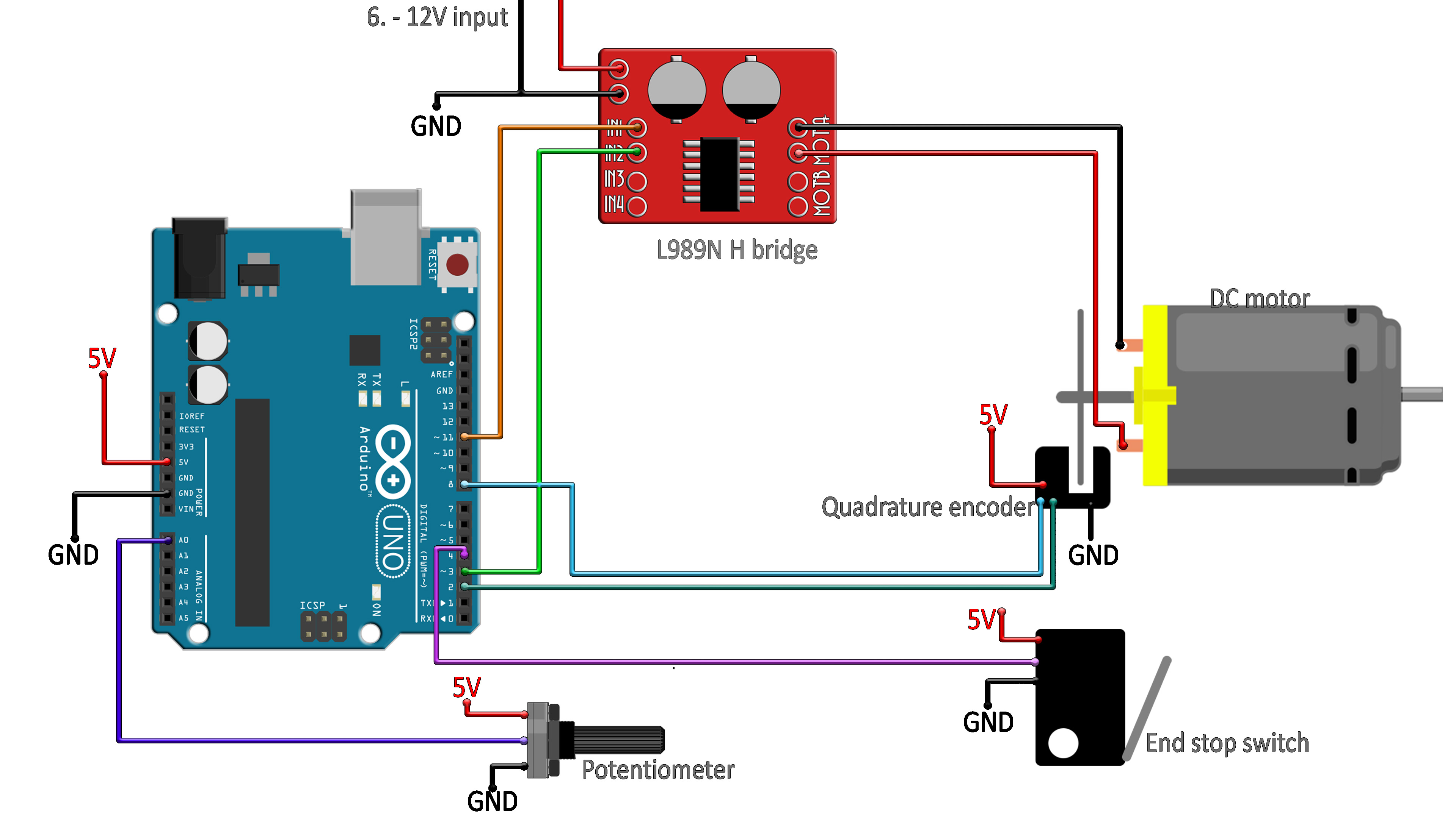
This is the code for the Arduino and PID control with optic encoded brushed DC motor control for one axis. You will need the PinChangeInterrupt library so download it from below and install it. Read all comments in the code in order to understand more. Downlaod the code from the link below or just copy the code from below as well.
//Include the libraries we need
#include <PinChangeInterrupt.h>
#include <PinChangeInterruptBoards.h>
#include <PinChangeInterruptPins.h>
#include <PinChangeInterruptSettings.h>
#include <TimerOne.h>                          // Timer one interrupts

//////////////////////////////////////////////////////////////
/////////////////////DEFINE PID constants/////////////////////
//////////////////////////////////////////////////////////////
int kp = 2, ki = 0.01, kd = 0.02;
//////////////////////////////////////////////////////////////
//////////////////////////////////////////////////////////////

int input, output, setpoint;
int iTerm = 0, lastInput = 0, dInput = 0, error = 0;
int outMin = -255, outMax = 255;
int sampleTime = 10;                                //This values is is milliseconds
volatile long encoderPos = 0;

//////////////////////////////////////////////////////////////
////////////////////Define the pins we use////////////////////
//////////////////////////////////////////////////////////////
#define Encoder_A      2                                    // Quadrature encoder A pin
#define Encoder_B      8                                    // Quadrature encoder B pin
#define Motor_CW       11                                   // PWM outputs to L298N H bridge motor driver module
#define Motor_CCW      3
#define led            13
#define END_stop       4

void setup(void)
{
  pinMode(Encoder_A, INPUT);                                // quadrature encoder input A
  pinMode(Encoder_B, INPUT);                                // quadrature encoder input B
  pinMode(END_stop, INPUT);                                 // Input from the end stop switch
  pinMode(led, OUTPUT);
  attachPCINT(digitalPinToPCINT(Encoder_A), encoder, FALLING);  // We update encoder position each falling edge detected in the interrumption
  TCCR2B = TCCR2B & 0b11111000 | 1;                             // set 31Kh PWM to prevent motor whine (timer 2)
  Timer1.initialize(sampleTime * 1000);                         // setup timer 1
  Timer1.attachInterrupt(Compute);
  Serial.begin(115200);                                         //Just for debugging if you want to print values
  while(digitalRead(END_stop))
  {
    analogWrite(Motor_CW, 0);                                   // Rotate the motor CCW
    analogWrite(Motor_CCW, 255);
  }
  analogWrite(Motor_CW, 0);                                     // Stop the motor
  analogWrite(Motor_CCW, 0);
}

void Compute()
{
  setpoint = map(analogRead(0),0,1024,1024,0) * 110;            // setpoint position is made with a potentiometer but could be given by serial monitor or other...
  input = encoderPos;                                           // we get the data from the encoder interrumption
  error = setpoint - input;
  iTerm += ki * error * sampleTime;
  if (iTerm > outMax) iTerm = outMax;                           // prevent that the I term from PID gets too big
  else if (iTerm < outMin) iTerm = outMin;
  dInput = (input - lastInput) / sampleTime;
  output = kp * error + iTerm - kd * dInput;                    // The PID output is the sum of P I and D values
  if (output > outMax) output = outMax;                         // limit output to 0 and 255 for the analog write
  else if (output < outMin) output = outMin;
  lastInput = input;                                            //Remember to save the last input value for the next loop
  pwmOut(output);                                               //Change the analog write for the motor control
}

void pwmOut(int out) {                                          // to H-Bridge board
  if (out > 0) {
    analogWrite(Motor_CW, out);                                 // Rotate the motor CW
    analogWrite(Motor_CCW, 0);
  }
  else {
    analogWrite(Motor_CW, 0);
    analogWrite(Motor_CCW, abs(out));                           // Rotate the motor CCW
  }
}

void encoder()  {                                     // pulse and direction, direct port reading to save cycles
  if (PINB & 0b00000001)    encoderPos++;             // if(digitalRead(encodPinB1)==HIGH)   count ++; //We increase steps by 1
  else                      encoderPos--;             // if (digitalRead(encodPinB1)==LOW)   count --; //We decrease steps by 1
}

void loop(void)
{
  digitalWrite(led, !digitalRead(led));               // blink led or do something else...
  delay(200);
}


