
 About me
  History
  Let's learn
  Contact us
  Arduino tutorials
 Circuits tutorials
  Robotics tutorials
 Q&A
Q&A Blog
Blog  Arduino
  Circuits
 Robotics
  Modules
  Gadgets
  Printers
  Materials
  3D objects
  3D edit
  Donate
  Reviews
  Advertising


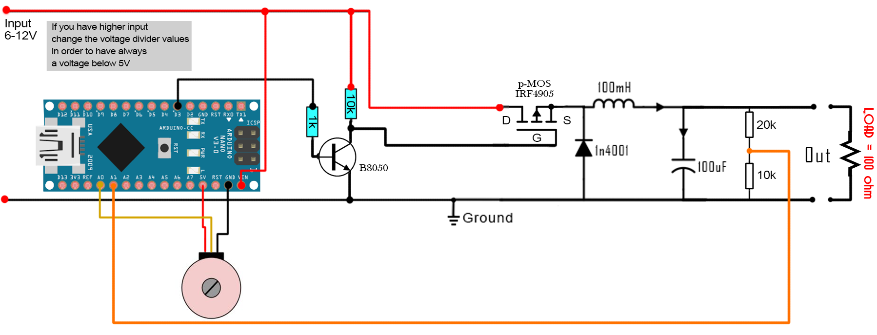
Buck converter - FEEDBACK
Connect everything as in the schematic below, download and upload the next code to your Arduino and start moving the potentiometer. try different LOAD values and observe the otput on the oscilloscope.
Download the
Or copy the next code
/* This is an example code for a BUCK converter circuit made with arduino
 * I've used arduino NANO. We have to set the timer of the PWM on pin D3
 * The feedback is connected to A1 and we set the desired voltage with a
 * potnetiometer connected to A0.
 *
 * Subscribe: http://www.youtube.com/c/electronoobs
 * webpage: http://www.electronoobs.com/eng_circuitos_tut10.php
 */


int potentiometer = A0;
int feedback = A1;
int PWM = 3;
int pwm = 0;

void setup() {
  pinMode(potentiometer, INPUT);
  pinMode(feedback, INPUT);
  pinMode(PWM, OUTPUT);
  TCCR2B = TCCR2B & B11111000 | B00000001;    // pin 3 and 11 PWM frequency of 31372.55 Hz
}

void loop() {
  float voltage = analogRead(potentiometer);
  float output  = analogRead(feedback);

  if (voltage > output)
   {
    pwm = pwm-1;
    pwm = constrain(pwm, 1, 254);
   }

  if (voltage < output)
   {
    pwm = pwm+1;
    pwm = constrain(pwm, 1, 254);
   }

   analogWrite(PWM,pwm);
}